Mitsubishi Eclipse. Manual - part 496


  Index      Mitsubishi     Mitsubishi Eclipse - service repair manual 2004 year


Search            


Content   ..  494  495  496  497   ..


Mitsubishi Eclipse. Manual - part 496


MULTIPORT FUEL INJECTION (MFI) DIAGNOSIS

TSB Revision

MULTIPORT FUEL INJECTION (MFI) <3.0L>

13B-527

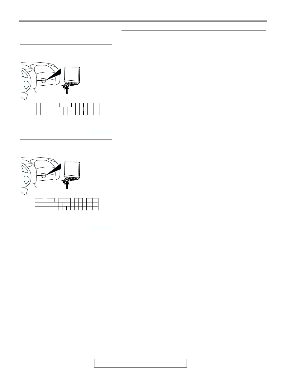
STEP 7. Check connector C-51 at ECM <M/T> or connector 
C-52 at PCM <A/T> for damage.
Q: Is the connector in good condition?

YES : Go to Step 8.
NO :  Repair or replace it. Refer to GROUP 00E, Harness 

Connector Inspection 

P.00E-2

. Then go to Step 10.

AK300458

2

3

4

5

6

7

8

9

11

12

13

14

15

16

17

18

19

20

30

21

22

23

24

25

26

27

28

29

31

32

33

34

35

1

10

CONNECTOR: C-52 <A/T>

C-52 (GR)

AB

HARNESS CONNECTOR:
COMPONENT SIDE

AK300443

2

3

4

5

6

7

8

9

11

12

13

14

15

16

17

18

19

20

30

21

22

23

24

25

26

27

28

29

31

32

33

34

35

1

10

CONNECTOR: C-51 <M/T>

C-51 (GR)

AB

HARNESS CONNECTOR:
COMPONENT SIDE

MULTIPORT FUEL INJECTION (MFI) DIAGNOSIS

TSB Revision

MULTIPORT FUEL INJECTION (MFI) <3.0L>

13B-528

STEP 8. Check for open circuit and short circuit to ground 
and harness damage between injector connector and ECM 
connector <M/T> or PCM connector <A/T>.

a. Check the harness wire between injector connector B-02 

(terminal No. 2) and ECM connector C-51 (terminal No. 9) 
<M/T> or PCM connector C-52 (terminal No. 9) <A/T> when 
checking No. 2 cylinder.

b. Check the harness wire between injector connector B-06 

(terminal No. 2) and ECM connector C-51 (terminal No. 2) 
<M/T> or PCM connector C-52 (terminal No. 2) <A/T> when 
checking No. 4 cylinder.

c. Check the harness wire between injector connector B-25 

(terminal No. 2) and ECM connector C-51 (terminal No. 25) 
<M/T> or PCM connector C-52 (terminal No. 25) <A/T> 
when checking No. 6 cylinder.

Q: Is the harness wire in good condition?

YES : Go to Step 9.
NO :  Repair it. Then go to Step 10.

AK300753

1

2

CONNECTORS: B-02, B-06, B-25

AB

B-02 (GR)

B-06 (GR) B-25 (GR)

HARNESS CONNECTOR:
COMPONENT SIDE

AK300458

2

3

4

5

6

7

8

9

11

12

13

14

15

16

17

18

19

20

30

21

22

23

24

25

26

27

28

29

31

32

33

34

35

1

10

CONNECTOR: C-52 <A/T>

C-52 (GR)

AB

HARNESS CONNECTOR:
COMPONENT SIDE

AK300443

2

3

4

5

6

7

8

9

11

12

13

14

15

16

17

18

19

20

30

21

22

23

24

25

26

27

28

29

31

32

33

34

35

1

10

CONNECTOR: C-51 <M/T>

C-51 (GR)

AB

HARNESS CONNECTOR:
COMPONENT SIDE

MULTIPORT FUEL INJECTION (MFI) DIAGNOSIS

TSB Revision

MULTIPORT FUEL INJECTION (MFI) <3.0L>

13B-529

STEP 9. Using the oscilloscope, check the injector.
(1) Disconnect the injector connector B-02 <No. 2 cylinder> or 

B-06 <No.  4 cylinder> or B-25 <No. 6 cylinder> and 
connect the test harness special tool (MB991348) 
inbetween. (All terminals should be connected)

(2) Connect the oscilloscope probe to the injector side 

connector terminal No. 2.
NOTE: When measuring with the ECM or PCM side con-
nector, connect an oscilloscope probe to the each of the fol-
lowing terminals.

.

ECM or PCM terminal No. 9 when checking No. 2 cylin-
der.

ECM or PCM terminal No. 2 when checking No. 4 cylin-
der.

ECM or PCM terminal No. 25 when checking No. 6 cyl-
inder.

(3) Start the engine and run at idle.
(4) Measure the waveform.

• The waveform should show a normal pattern similar to 

the illustration.

(5) Turn the ignition switch to the "LOCK" (OFF) position.
Q: Is the waveform normal?

YES : It can be assumed that this malfunction is intermittent. 

Refer to GROUP 00, How to Use Troubleshooting/ 
Inspection Service Points 

P.00-6

.

NO :  Replace the ECM or PCM. Then go to Step 10.

STEP 10. Test the OBD-II drive cycle.
(1) Carry out a test drive with the drive cycle pattern. Refer to 

Diagnostic Function 

− OBD-II Drive Cycle − Procedure 6 − 

Other Monitor 

P.13B-7

.

(2) Check the diagnostic trouble code (DTC).
Q: Are DTC P0202, P0204 and P0206 sets?

YES : Retry the troubleshooting.
NO :  The inspection is complete.

AK300753

1

2

CONNECTORS: B-02, B-06, B-25

AB

B-02 (GR)

B-06 (GR) B-25 (GR)

HARNESS CONNECTOR:
COMPONENT SIDE

AK102980

1 2

INJECTOR
CONNECTOR

MB991348

AB

OSCILLOSCOPE

AKX01557 AB

A

NORMAL  WAVEFORM

A:INJECTOR DRIVE TIME

MULTIPORT FUEL INJECTION (MFI) DIAGNOSIS

TSB Revision

MULTIPORT FUEL INJECTION (MFI) <3.0L>

13B-530

DTC P0300: Random/Multiple Cylinder Misfire Detected

.

Random Misfire Circuit

• Refer to DTC P0201, P0203, P0205 − Injector 

Circuit 

P.13B-510

.

• Refer to DTC P0202, P0204, P0206 − Injector 

Circuit 

P.13B-521

.

.

CIRCUIT OPERATION

• Refer to DTC P0201, P0203, P0205 − Injector 

Circuit 

P.13B-510

.

• Refer to DTC P0202, P0204, P0206 − Injector 

Circuit 

P.13B-521

.

.

TECHNICAL DESCRIPTION

• If a misfire occurs while the engine is running, the 

engine speed changes for an instant.

• The ECM <M/T> or PCM <A/T> checks for such 

changes in engine speed.

.

DESCRIPTIONS OF MONITOR METHODS
Monitor angular acceleration of crankshaft and 

detect malfunction when negative variation of the 
angular acceleration is large.

.

MONITOR EXECUTION
Continuous

.

MONITOR EXECUTION CONDITIONS (Other 
monitor and Sensor)

Other Monitor (There is no temporary DTC stored 

in memory for the item monitored below)

• Not applicable

Sensor (The sensor below is determined to be 

normal)

• Camshaft position sensor

• Volume airflow sensor

• Engine coolant temperature sensor

• Intake air temperature sensor

• Barometric pressure sensor

• Throttle position sensor

.


Content   ..  494  495  496  497   ..