Mitsubishi Eclipse. Manual - part 467


  Index      Mitsubishi     Mitsubishi Eclipse - service repair manual 2004 year


Search            


Content   ..  465  466  467  468   ..


Mitsubishi Eclipse. Manual - part 467


MULTIPORT FUEL INJECTION (MFI) DIAGNOSIS

TSB Revision

MULTIPORT FUEL INJECTION (MFI) <3.0L>

13B-411

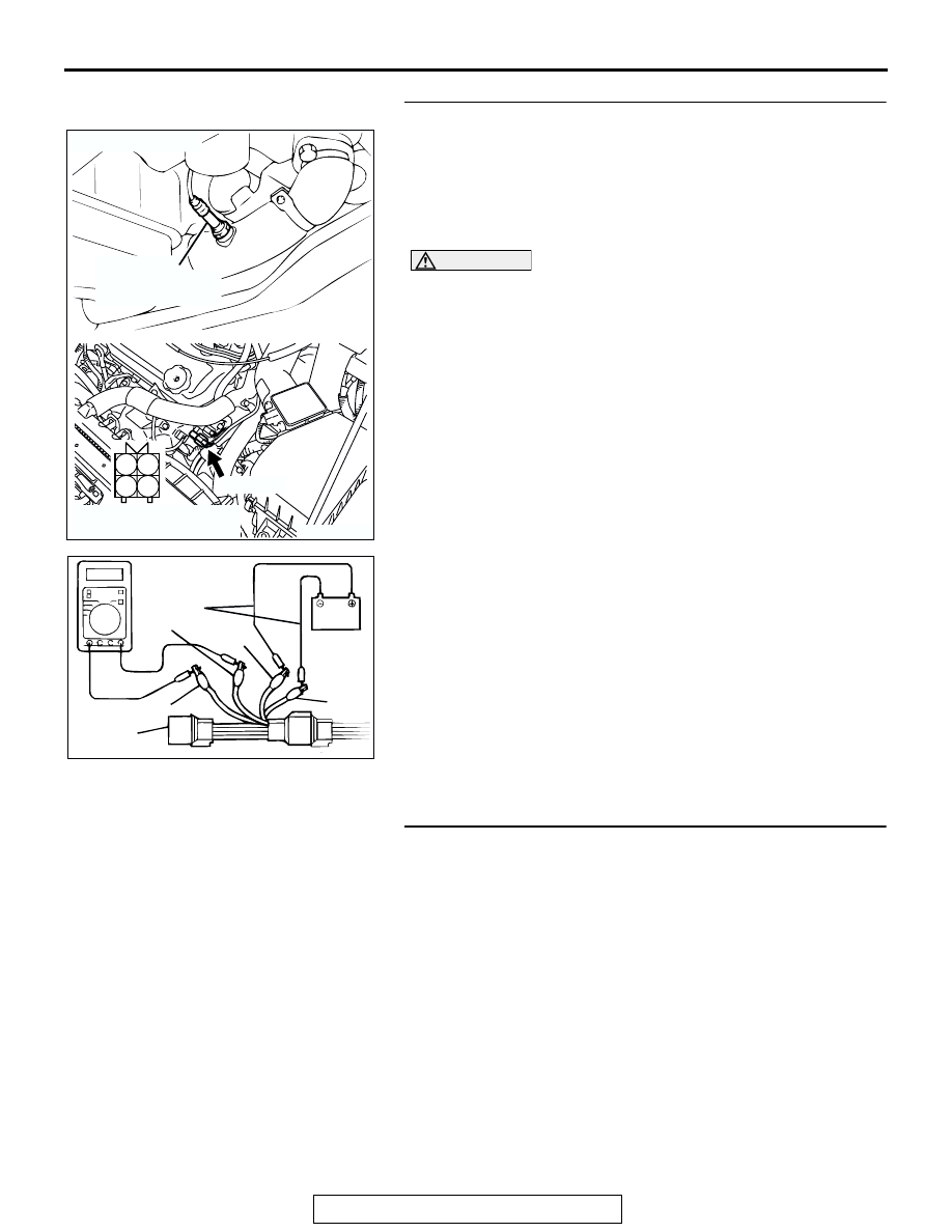
STEP 14. Check the left bank heated oxygen sensor (rear).
(1) Disconnect the left bank heated oxygen sensor (rear) 

connector B-23 and connect test harness special tool, 
MB991316, to the connector on the left bank heated oxygen 
sensor (front) side.

(2) Warm up the engine until engine coolant 80

°C (176°F) or 

higher.

CAUTION

Be very careful when connecting the jumper wires; incor-
rect connection can damage the left bank heated oxygen 
sensor (rear).

(3) Use the jumper wires to connect terminal No. 1 (red clip) to 

the positive battery terminal and terminal No. 3 (blue clip) to 
the negative battery terminal.

(4) Connect a digital volt meter between terminal No. 2 (black 

clip) and terminal No. 4 (white clip).

(5) While repeatedly revving the engine, measure the left bank 

heated oxygen sensor (rear) output voltage.

Standard value: 0.6 

 1.0 volt

Q: Is the voltage between 0.6 and 1.0 volt?

YES : Replace the ECM or PCM. Then go to Step 15.
NO :  Replace the left bank heated oxygen sensor (rear). 

Then go to Step 15.

STEP 15. Test the OBD-II drive cycle.
(1) Carry out a test drive with the drive cycle pattern. Refer to 

Diagnostic Function 

− OBD-II Drive Cycle − Procedure 6 − 

Other Monitor 

P.13B-7

.

(2) Check the diagnostic trouble code (DTC).
Q: Is DTC P0156 set?

YES : Retry the troubleshooting.
NO :  The inspection is complete.

AK300410

1

2

3

4

LEFT BANK 
HEATED OXYGEN
SENSOR (REAR)

CONNECTOR: B-23

AB

B-23 (GR)

HARNESS CONNECTOR:
COMPONENT SIDE

AKX01625 AB

BLUE

JUMPER
WIRES

BLACK

RED

WHITE

MB991316

MULTIPORT FUEL INJECTION (MFI) DIAGNOSIS

TSB Revision

MULTIPORT FUEL INJECTION (MFI) <3.0L>

13B-412

DTC P0157: Heated Oxygen Sensor Circuit Low Voltage (bank 2, sensor 2)

AK103016

BLA

C

K

BLUE

YELLO

W

3 4

1 2

FROM MFI RELAY

LEFT BANK HEATED
OXYGEN SENSOR (REAR)

TO ECM
OR PCM

73 <M/T>*2
73 <A/T>*4

49 <M/T>*1
57 <A/T>*3

1

3

2

4

     B-23
MU802665

NOTE
*1:ECM connector C-58 <M/T>
*2:ECM connector C-62 <M/T>
*3:PCM connector C-55 <A/T>
*4:PCM connector C-59 <A/T>

ENGINE CONTROL
MODULE (ECM) <M/T>
OR
POWERTRAIN CONTROL
MODULE (PCM) <A/T>

65

43
50

42
49

41
48
60 61

64

46 47
58 59
67 68

45

56
66

52

51

44

53

62

54

63

57

55

C-58 <M/T>
(MU803782)

C-55 <A/T>
(MU803781)

42 43
48 49 50 51 52 53 54 55 56 57

46

45

44

58 59

60 61 62 63

64 65 66

47

41

98

78

71

88 89

76 77

72
79
91

73
80

74

75

81
92

82 83
93

84 85

94

86 87

95 96

90

80

87

81

94

85

82

84

93

86

98

99

74

92

73

83

88

91

95

97

96

100

89

78

71

90

76 77

75

72
79

97

C-62 <M/T>
(MU803783)

C-59 <A/T>
(MU803782)

Left Bank Heated Oxygen Sensor (rear) Circuit

MULTIPORT FUEL INJECTION (MFI) DIAGNOSIS

TSB Revision

MULTIPORT FUEL INJECTION (MFI) <3.0L>

13B-413

.

CIRCUIT OPERATION

• A voltage corresponding to the oxygen concen-

tration in the exhaust gas is sent to the ECM (ter-
minal No. 73) <M/T> or PCM (terminal No. 73) 
<A/T> from the output terminal (terminal No. 4) of 
the left bank heated oxygen sensor (rear).

• Terminal No. 2 of the left bank heated oxygen 

sensor (rear) is grounded with ECM (terminal No. 
49) <M/T> or PCM (terminal No. 57) <A/T>.

.

TECHNICAL DESCRIPTION

• The output signal of the heated oxygen sensor 

(front) is compensated by the output signal of the 
left bank heated oxygen sensor (rear).

• The ECM <M/T> or PCM <A/T> checks for an 

open circuit in the left bank heated oxygen sensor 
(rear) output line.

.

DESCRIPTIONS OF MONITOR METHODS
Left bank heated oxygen sensor (rear) output voltage 

stays low when air/fuel ratio is forced to be rich. 
The above procedure is repeated when oxygen 
sensor is inactive.

.

MONITOR EXECUTION
Continuous

.

MONITOR EXECUTION CONDITIONS (Other 
monitor and Sensor)

Other Monitor (There is no temporary DTC stored 

in memory for the item monitored below)

• Heated oxygen sensor heater (front) monitor

• Heated oxygen sensor heater (rear) monitor

• Air/fuel ratio feedback monitor

Sensor (The sensor below is determined to be 

normal)

• Volume airflow sensor

• Engine coolant temperature sensor

• Intake air temperature sensor

• Barometric pressure sensor

.

AK300058

LEFT BANK 
HEATED OXYGEN
SENSOR (REAR)

CONNECTOR: B-23

AB

B-23 (GR)

AK300244

CONNECTORS: C-55, C-59 <A/T>

AD

PCM

C-55 (GR)

C-59 (GR)

AK300091

CONNECTORS: C-58, C-62 <M/T>

ECM

AD

C-58 (GR)

C-62 (GR)

MULTIPORT FUEL INJECTION (MFI) DIAGNOSIS

TSB Revision

MULTIPORT FUEL INJECTION (MFI) <3.0L>

13B-414

DTC SET CONDITIONS

Logic Flow Chart

.

Check Conditions

• 3 minutes or more have passed since the starting 

sequence was completed.

• Left bank heated oxygen sensor (rear) signal volt-

age has continued to be 0.15 volt or lower.

• Engine coolant temperature is higher than 76°C 

(169

°F).

• Engine speed is higher than 1,200 r/min.

• Volumetric efficiency is higher than 25 percent.

• Volume airflow sensor output frequency is 75 Hz 

or more.

START

V

F

 > =4.5V

2secs HAS PASSED

YES

YES

YES

NO

NO

NO

MALFUNCTION

MONITORING

CONDITIONS

YES

NO

MONITORING

CONDITIONS

+5V ON

AK301440

V

F

 < 0.15V

10secs HAS PASSED

YES

YES

NO

NO

END

MALFUNCTION

GOOD

MODULATE A/F CONDITION TO RICH


Content   ..  465  466  467  468   ..