Mitsubishi Eclipse. Manual - part 409


  Index      Mitsubishi     Mitsubishi Eclipse - service repair manual 2004 year


Search            


Content   ..  407  408  409  410   ..


Mitsubishi Eclipse. Manual - part 409


MULTIPORT FUEL INJECTION (MFI) DIAGNOSIS

TSB Revision

MULTIPORT FUEL INJECTION (MFI) <3.0L>

13B-179

.

CIRCUIT OPERATION

• A 5-volt power supply is applied on the TPS 

power terminal (terminal No. 4) from the ECM 
(terminal No. 42) <M/T> or PCM (terminal No. 46) 
<A/T>.
The ground terminal (terminal No. 1) is grounded 
with ECM (terminal No. 49) <M/T> or PCM (termi-
nal No. 57) <A/T>.

• When the throttle valve shaft is turned from the 

idle position to the fully opened position, the 
resistor between the TPS output terminal (termi-
nal No. 3) and ground terminal will increase 
according to the rotation. 

.

TECHNICAL DESCRIPTION

• The TPS outputs voltage which corresponds to 

the throttle valve opening angle.

• The ECM <M/T> or PCM <A/T> checks whether 

the voltage is within a specified range. In addi-
tion, it checks that the voltage output does not 
become too high while the engine is at idle.

.

DESCRIPTIONS OF MONITOR METHODS
throttle position sensor (main) output voltage is out of 

specified range.

.

MONITOR EXECUTION
Continuous

.

MONITOR EXECUTION CONDITIONS (Other 
monitor and Sensor)

Other Monitor (There is no temporary DTC stored 

in memory for the item monitored below)

• Not applicable

Sensor (The sensor below is determined to be 

normal)

• Not applicable

.

AK300091

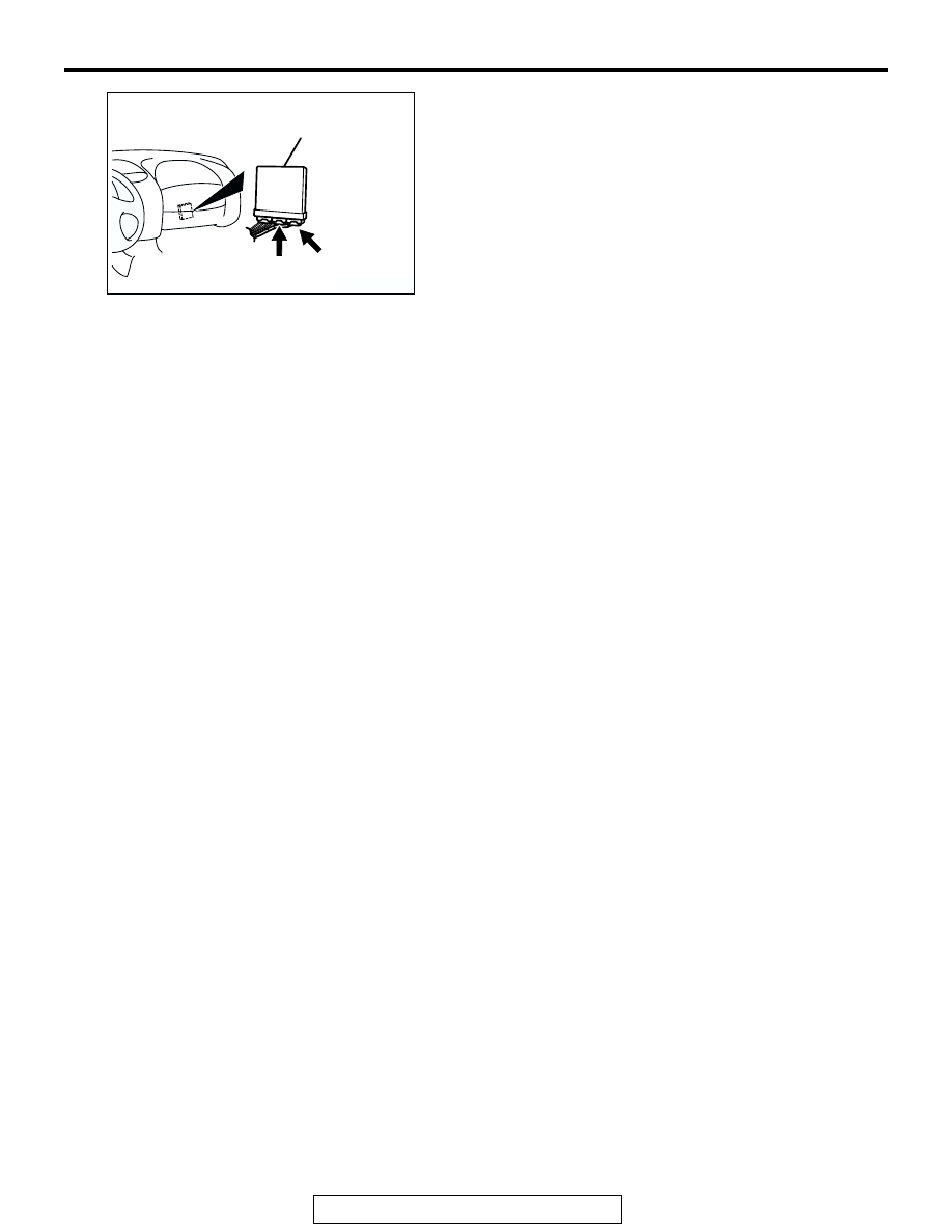
CONNECTORS: C-58, C-62 <M/T>

ECM

AD

C-58 (GR)

C-62 (GR)

MULTIPORT FUEL INJECTION (MFI) DIAGNOSIS

TSB Revision

MULTIPORT FUEL INJECTION (MFI) <3.0L>

13B-180

DTC SET CONDITIONS

Logic Flow Chart

.

Check Conditions

• 2 seconds or more have passed since the start-

ing sequence was completed.

Judgement Criteria

• TPS output voltage has continued to be 0.2 volt 

or lower for 2 seconds.

.

OBD-ll DRIVE CYCLE PATTERN
None.

.

TROUBLESHOOTING HINTS (The most likely 
causes for this code to be set are: )

• TPS failed or maladjusted.

• Open or shorted TPS circuit, or loose connector.

• ECM failed. <M/T>

• PCM failed. <A/T>

DIAGNOSIS

Required Special Tools:

• MB991958: Scan Tool (MUT-III Sub Assembly)

• MB991824: V.C.I.

• MB991827: USB Cable

• MB991911: Main Harness B

START

END

NO

NO

YES

YES

MALFUNCTION

GOOD

CONTINUOUS

FAILURE FOR 2 secs

OUTPUT VOLTAGE

< 0.2V

NO

YES

MONITORING

CONDITIONS

AK301429

MULTIPORT FUEL INJECTION (MFI) DIAGNOSIS

TSB Revision

MULTIPORT FUEL INJECTION (MFI) <3.0L>

13B-181

STEP 1. Using scan tool MB991958, check data list item 14: 
Throttle Position Sensor.

CAUTION

To prevent damage to scan tool MB991958, always turn the 
ignition switch to the "LOCK" (OFF) position before con-
necting or disconnecting scan tool MB991958.
(1) Connect scan tool MB991958 to the data link connector.
(2) Turn the ignition switch to the "ON" position.
(3) Set scan tool MB991958 to the data reading mode for item 

14, Throttle Position Sensor.

• With the throttle valve in the idle position, voltage should 

be between 0.535 and 0.735 volt.

• With the throttle valve in the full-open position, voltage 

should be between 4.5 and 5.5 volts.

(4) Turn the ignition switch to the "LOCK" (OFF) position.
Q: Is the sensor operating properly?

YES : It can be assumed that this malfunction is intermittent. 

Refer to GROUP 00, How to Use Troubleshooting/ 
Inspection Service Points 

P.00-6

.

NO :  Go to Step 2.

STEP 2. Check connector B-07 at throttle position sensor 
for damage.
Q: Is the connector in good condition?

YES : Go to Step 3.
NO :  Repair or replace it. Refer to GROUP 00E, Harness 

Connector Inspection 

P.00E-2

. Then go to Step 11.

AK300810

AB

MB991911

16-PIN

MB991827

MB991824 

AK300434

2 1

3

4

CONNECTOR: B-07

AB

B-07 (B)

HARNESS CONNECTOR:
COMPONENT SIDE

MULTIPORT FUEL INJECTION (MFI) DIAGNOSIS

TSB Revision

MULTIPORT FUEL INJECTION (MFI) <3.0L>

13B-182

STEP 3. Check the sensor supply voltage at throttle 
position sensor harness side connector B-07.
(1) Disconnect the connector B-07 and measure at the harness 

side.

(2) Turn the ignition switch to the "ON" position.

(3) Measure the voltage between terminal No. 4 and ground.

• Voltage should be between 4.8 and 5.2 volts.

(4) Turn the ignition switch to the "LOCK" (OFF) position.
Q: Is the measured voltage between 4.8 and 5.2 volts?

YES : Go to Step 6.
NO :  Go to Step 4.

AK300434

2 1

3

4

CONNECTOR: B-07

AB

B-07 (B)

HARNESS CONNECTOR:
COMPONENT SIDE

AK000236 AG

B-07 HERNESS 
CONNECTOR: 
COMPONENT SIDE

4 3 2 1


Content   ..  407  408  409  410   ..