Mitsubishi Eclipse. Manual - part 388


  Index      Mitsubishi     Mitsubishi Eclipse - service repair manual 2004 year


Search            


Content   ..  386  387  388  389   ..


Mitsubishi Eclipse. Manual - part 388


MULTIPORT FUEL INJECTION (MFI) DIAGNOSIS

TSB Revision

MULTIPORT FUEL INJECTION (MFI) <3.0L>

13B-95

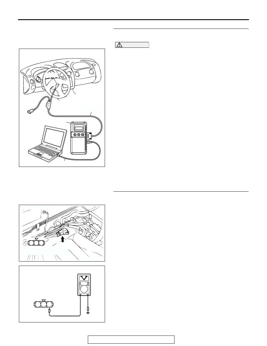
STEP 4. Using scan tool MB991958, check data list item 95: 
Manifold Absolute Pressure Sensor.

CAUTION

To prevent damage to scan tool MB991958, always turn the 
ignition switch to the "LOCK" (OFF) position before con-
necting or disconnecting scan tool MB991958.
(1) Connect scan tool MB991958 to the data link connector.
(2) Turn the ignition switch to the "ON" position.
(3) Set scan tool MB991958 to the data reading mode for item 

95, Manifold Absolute Pressure Sensor.

• When altitude is 0 m (0 foot), 101 kPa (29.8 in.Hg).

• When altitude is 600 m (1,969 feet), 95 kPa (28.1 in.Hg).

• When altitude is 1,200 m (3,937 feet), 88 kPa (26.0 

in.Hg).

• When altitude is 1,800 m (5,906 feet), 81 kPa (23.9 

in.Hg).

(4) Start the engine.

• When the engine is idling, 18 − 38 kPa (5.3 − 11.2 

in.Hg).

• When the engine is suddenly revved, manifold absolute 

pressure increases.

(5) Turn the ignition switch to the "LOCK" (OFF) position.
Q: Is the sensor operating properly?

YES : It can be assumed that this malfunction is intermittent. 

Refer to GROUP 00, How to Use Troubleshooting/ 
Inspection Service Points 

P.00-6

.

NO :  Replace the ECM or PCM. Then go to Step 12.

STEP 5. Measure the sensor supply voltage at manifold 
absolute pressure sensor connector B-04 by backprobing.
(1) Do not disconnect the connector B-04.
(2) Turn the ignition switch to the "ON" position.

(3) Measure the voltage between terminal No. 3 and ground by 

backprobing.

• Voltage should be between 4.8 and 5.2 volts.

(4) Turn the ignition switch to the "LOCK" (OFF) position.
Q: Is the measured voltage between 4.8 and 5.2 volts?

YES : Go to Step 7.
NO :  Go to Step 6.

AK300810

AB

MB991911

16-PIN

MB991827

MB991824 

AK103763

2 1

3

CONNECTOR: B-04

AC

B-04(B)

HARNESS CONNECTOR:
COMPONENT SIDE

3

2

1

AK203036

B-04 HARNESS 
CONNECTOR: 
HARNESS SIDE

AE

MULTIPORT FUEL INJECTION (MFI) DIAGNOSIS

TSB Revision

MULTIPORT FUEL INJECTION (MFI) <3.0L>

13B-96

STEP 6. Check connector C-58 at ECM <M/T> or C-55 at 
PCM <A/T> for damage.
Q: Is the connector in good condition?

YES : Replace the ECM or PCM. Then go to Step 12.
NO :  Repair or replace it. Refer to GROUP 00E, Harness 

Connector Inspection 

P.00E-2

. Then go to Step 12.

AK300462

42

43

48

49

50

51

52

53

54

55

56

57

46 45 44

58

59

60

61

62

63

64

65

66

47

41

CONNECTOR: C-55 <A/T>

C-55 (GR)

AB

HARNESS CONNECTOR:
COMPONENT SIDE

AK300748

65

43
50

42
49

41
48
60

61

64

46

47

58

59

67

68

45

56
66

52 51

44

53

62

54

63

57

55

CONNECTOR: C-58 <M/T>

AB

C-58 (GR)

HARNESS CONNECTOR:
COMPONENT SIDE

MULTIPORT FUEL INJECTION (MFI) DIAGNOSIS

TSB Revision

MULTIPORT FUEL INJECTION (MFI) <3.0L>

13B-97

STEP 7. Measure the ground voltage at manifold absolute 
pressure sensor connector B-04 by backprobing.
(1) Do not disconnect the connector B-04.
(2) Turn the ignition switch to the "ON" position.

(3) Measure the voltage between terminal No. 2 and ground by 

backprobing.

• Voltage should be 0.5 volt or less.

(4) Turn the ignition switch to the "LOCK" (OFF) position.
Q: Is the measured voltage 0.5 volt or less?

YES : Go to Step 10.
NO :  Go to Step 8.

AK103763

2 1

3

CONNECTOR: B-04

AC

B-04(B)

HARNESS CONNECTOR:
COMPONENT SIDE

3

2

1

AK203038

B-04 HARNESS 
CONNECTOR: 
HARNESS SIDE

AE

MULTIPORT FUEL INJECTION (MFI) DIAGNOSIS

TSB Revision

MULTIPORT FUEL INJECTION (MFI) <3.0L>

13B-98

STEP 8. Check connector B-04 at the manifold absolute 
pressure sensor and connector C-58 at ECM <M/T> or C-55 
at PCM <A/T> for damage.
Q: Is the connector in good condition?

YES : Go to Step 9.
NO :  Repair or replace it. Refer to GROUP 00E, Harness 

Connector Inspection 

P.00E-2

. Then go to Step 12.

AK103763

2 1

3

CONNECTOR: B-04

AC

B-04(B)

HARNESS CONNECTOR:
COMPONENT SIDE

AK300462

42

43

48

49

50

51

52

53

54

55

56

57

46 45 44

58

59

60

61

62

63

64

65

66

47

41

CONNECTOR: C-55 <A/T>

C-55 (GR)

AB

HARNESS CONNECTOR:
COMPONENT SIDE

AK300748

65

43
50

42
49

41
48
60

61

64

46

47

58

59

67

68

45

56
66

52 51

44

53

62

54

63

57

55

CONNECTOR: C-58 <M/T>

AB

C-58 (GR)

HARNESS CONNECTOR:
COMPONENT SIDE


Content   ..  386  387  388  389   ..