Mitsubishi Eclipse. Manual - part 387
MULTIPORT FUEL INJECTION (MFI) DIAGNOSIS
TSB Revision
MULTIPORT FUEL INJECTION (MFI) <3.0L>
13B-91
DTC SET CONDITIONS
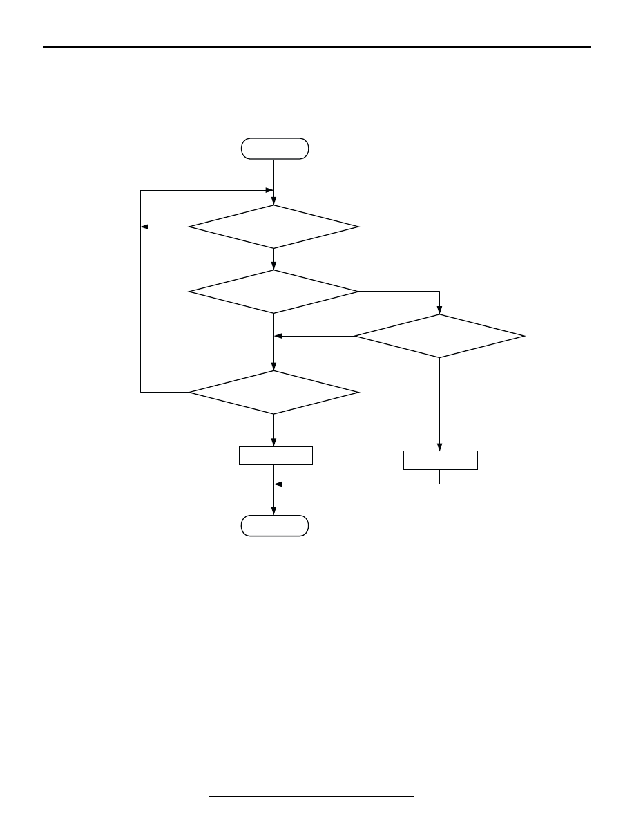
Logic Flow Chart
.
Check Conditions
• 8 minutes or more have passed since the starting
sequence was completed, when the engine cool-
ant temperature at engine start is 0
°C (32°F) or
lower.
Judgement Criteria
• Manifold absolute pressure is 117 kPa (34.6
in.Hg) or higher for 2 seconds.
.
OBD-ll DRIVE CYCLE PATTERN
Refer to Diagnostic Function
− OBD-ll Drive Cycle −
Procedure 6
.
.
TROUBLESHOOTING HINTS (The most likely
causes for this code to be set are: )
• Manifold Absolute pressure sensor failed.
• Open manifold absolute pressure sensor circuit,
or connector damage.
• ECM <M/T> failed.
• PCM <M/T> failed.
DIAGNOSIS
Required Special Tools:
• MB991958: Scan Tool (MUT-III Sub Assembly)
YES
YES
YES
YES
NO
NO
NO
NO
MONITORING
CONDITIONS
PRESSURE < 4.9kPa (1.4in.Hg)
PRESSURE > 117kPa (34.6in.Hg)
CONTINUOUS
FAILURE FOR 2secs
MALFUNCTION
END
GOOD
START
AK301416