Mitsubishi Eclipse. Manual - part 320


  Index      Mitsubishi     Mitsubishi Eclipse - service repair manual 2004 year


Search            


Content   ..  318  319  320  321   ..


Mitsubishi Eclipse. Manual - part 320


MULTIPORT FUEL INJECTION (MFI) DIAGNOSIS

TSB Revision

MULTIPORT FUEL INJECTION (MFI) <2.4L>

13A-773

STEP 3. Check the engine idling state.
Q: Is it hunting remarkably?

YES : Go to Step 4.
NO :  Go to Step 5.

STEP 4. Check the following items.
(1) Carry out the following cleaning.

a. Clean the throttle valve area. Refer to 

P.13A-926

.

(2) After cleaning, confirm that the malfunction symptom is 

eliminated.

Q: Is the malfunction symptom resolved?

YES : The check is completed.
NO :  Check the following items, and repair or replace the 

defective items.

a. Broken intake manifold gasket.
b. Broken air intake hose.

c. Broken vacuum hose.

d. Positive crankcase ventilation valve does not 

operate.

Then confirm that the malfunction symptom is 

eliminated.

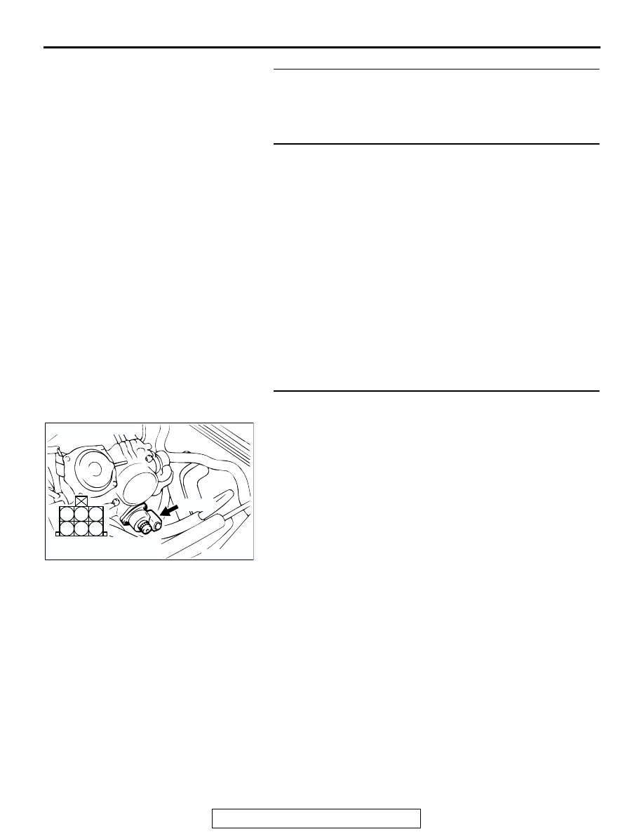
STEP 5. Check the idle air control (IAC) motor operation 
sound.
(1) Check that the engine coolant temperature is 20

°C (68°F) 

or below.
NOTE: Disconnecting the engine coolant temperature sen-
sor connector and connecting the harness side of the con-
nector to another engine coolant temperature sensor that is 
at 20

°

C (68

°

F) or below is also okay.

(2) Check the operation sound of the IAC motor can be heard 

after the ignition is switched to the "ON" position (but 
without starting the engine).

• An operation sound is heard.

(3) Turn the ignition switch to the "LOCK" (OFF) position.
Q: Did you hear the operation sound?

YES : Go to Step 6.
NO :  Refer to, DTC P0506 

− Idle Control System RPM 

Lower Than Expected 

P.13A-625

, DTC P0507 

− Idle 

Control System RPM Higher Than Expected 

P.13A-640

.

AK300408

1

2

3

4

5

6

CONNECTOR: B-34

AB

B-34 (B)

HARNESS CONNECTOR:
COMPONENT SIDE

MULTIPORT FUEL INJECTION (MFI) DIAGNOSIS

TSB Revision

MULTIPORT FUEL INJECTION (MFI) <2.4L>

13A-774

STEP 6. Using scan tool MB991958, check actuator test 
items 01, 02, 03, 04: Injector.

CAUTION

To prevent damage to scan tool MB991958, always turn the 
ignition switch to the "LOCK" (OFF) position before con-
necting or disconnecting scan tool MB991958.
(1) Connect scan tool MB991958 to the data link connector.
(2) Turn the ignition switch to the "ON" position.
(3) Check following items in the actuator test. Refer to, Actuator 

Test Reference Table 

P.13A-903

.

a. Item 01, 02, 03, 04: Injector.

(4) Turn the ignition switch to the "LOCK" (OFF) position.
Q: Is the actuator operating properly?

YES : Go to Step 7.
NO :  Refer to, DTC P0201, P0202, P0203, P0204 

− 

Injector Circuit Malfunction 

P.13A-377

.

STEP 7. Using scan tool MB991958, check data list.
(1) Turn the ignition switch to the "ON" position.
(2) Check the following items in the data list. Refer to, Data List 

Reference Table 

P.13A-892

.

a. Item 13: Intake Air Temperature Sensor.
b. Item 25: Barometric Pressure Sensor.

c. Item 21: Engine Coolant Temperature Sensor.

d. Item 59: Heated Oxygen Sensor (rear).
e. Item 11: Heated Oxygen Sensor (front).

f. Item 27: Power Steering Pressure Switch.

g. Item 28: A/C Switch.

(3) Turn the ignition switch to the "LOCK" (OFF) position.
Q: Are they operating properly?

YES : Go to Step 8.
NO :  Repair or replace. Then confirm that the malfunction 

symptom is eliminated.

AK300810

AB

MB991911

16-PIN

MB991827

MB991824 

AK300810

AB

MB991911

16-PIN

MB991827

MB991824 

MULTIPORT FUEL INJECTION (MFI) DIAGNOSIS

TSB Revision

MULTIPORT FUEL INJECTION (MFI) <2.4L>

13A-775

STEP 8. Using scan tool MB991958, check actuator test.
(1) Turn the ignition switch to the "ON" position.
(2) Check the following items in the actuator test. Refer to, 

Actuator Test Reference Table 

P.13A-903

.

a. Item 08: Evaporative Emission Purge Solenoid.
b. Item 10: EGR Vacuum Regulator Solenoid Valve.

(3) Turn the ignition switch to the "LOCK" (OFF) position.
Q: Are they operating properly?

YES : Go to Step 9.
NO :  Repair or replace. Then confirm that the malfunction 

symptom is eliminated.

STEP 9. Using scan tool MB991958, check data list.
(1) Turn the ignition switch to the "ON" position.
(2) Check the following items in the data list. Refer to, Data List 

Reference Table 

P.13A-892

.

a. Item 45: Idle Air Control Motor Position.

(3) Turn the ignition switch to the "LOCK" (OFF) position.
Q: Is the actuator operating properly?

YES : Go to Step 10.
NO :  Adjust the basic idle speed. Refer to, Basic Idle 

Speed Adjustment 

P.13A-928

. After adjusting, 

confirm.

AK300810

AB

MB991911

16-PIN

MB991827

MB991824 

AK300810

AB

MB991911

16-PIN

MB991827

MB991824 

MULTIPORT FUEL INJECTION (MFI) DIAGNOSIS

TSB Revision

MULTIPORT FUEL INJECTION (MFI) <2.4L>

13A-776

STEP 10. Using scan tool MB991958, check data list.
(1) Turn the ignition switch to the "ON" position.
(2) Check the following items of the data list. Refer to, Data List 

Reference Table 

P.13A-892

.

a. Item 11: Heated Oxygen Sensor (front).

• Voltage should fluctuate between 0 − 0.4 volt and 0.6 − 

1.0 volt while idling after the engine has been warmed.

(3) Turn the ignition switch to the "LOCK" (OFF) position.
Q: Is the sensor operating properly?

YES : Go to Step 12.
NO :  Go to Step 11.

STEP 11. Check the fuel pressure.
Refer to, Fuel Pressure Test 

P.13A-929

.

Q: Is the fuel pressure normal?

YES :  a. Check the following items, and repair or replace 

the defective items.

• Vacuum leak.

• Broken intake manifold gasket.

• Broken air intake hose.

• Broken vacuum hose.

• Positive crankcase ventilation valve does not 

operate.

b. Injector clogged.

Then confirm that the malfunction symptom is 
eliminated.

NO :  Repair or replace. Then confirm that the malfunction 

symptom is eliminated.

AK300810

AB

MB991911

16-PIN

MB991827

MB991824 


Content   ..  318  319  320  321   ..