Mitsubishi Eclipse. Manual - part 316


  Index      Mitsubishi     Mitsubishi Eclipse - service repair manual 2004 year


Search            


Content   ..  314  315  316  317   ..


Mitsubishi Eclipse. Manual - part 316


MULTIPORT FUEL INJECTION (MFI) DIAGNOSIS

TSB Revision

MULTIPORT FUEL INJECTION (MFI) <2.4L>

13A-757

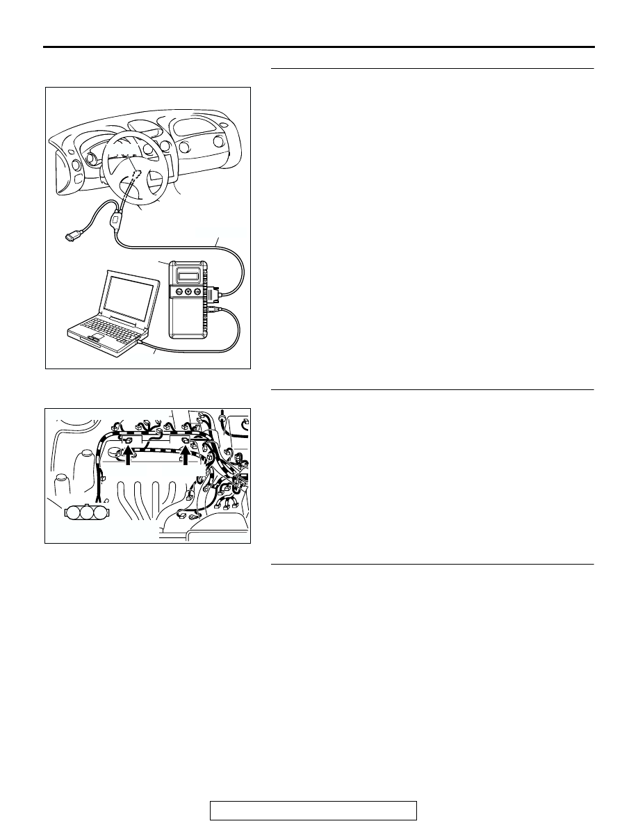
STEP 4. Using scan tool MB991958, check actuator test.
(1) Turn the ignition switch to the "ON" position.
(2) Check the following items in the actuator test. Refer to 

Actuator Test Reference Table 

P.13A-903

.

a. Item 07: Fuel pump.

(3) Turn the ignition switch to the "LOCK" (OFF) position.
Q: Is the actuator operating properly?

YES : Go to Step 5.
NO :  Repair or replace. Then confirm that the malfunction 

symptom is eliminated.

STEP 5. Check the ignition system.
(1) Connect the timing light to terminal No. 1 of the ignition coil 

connector B-16 or B-20, in order.

(2) Crank the engine.

• The timing light flashes.

(3) Turn the ignition switch to the "LOCK" (OFF) position.
Q: Does the timing light flash?

YES : Go to Step 6.
NO :  Refer to INSPECTION PROCEDURE 33 

− Ignition 

Circuit System 

P.13A-877

.

STEP 6. Check the ignition timing.
(1) Check the ignition timing at cranking.

Standard value: 5

° BTDC ± 3°

Q: Is the ignition timing normal?

YES : Go to Step 7.
NO :  Check that the crankshaft position sensor and timing 

belt cover are in the correct position. Then confirm 
that the malfunction symptom is eliminated.

AK300810

AB

MB991911

16-PIN

MB991827

MB991824 

AK300742

1

2

3

CONNECTORS: B-16, B-21

AB

B-21 (GR)

B-16 (GR)

HARNESS CONNECTOR:
COMPONENT SIDE

MULTIPORT FUEL INJECTION (MFI) DIAGNOSIS

TSB Revision

MULTIPORT FUEL INJECTION (MFI) <2.4L>

13A-758

STEP 7. Check harness connector B-01 or B-02 or B-05 or 
B-06 at injector for damage.
Q: Is the harness connector in good condition?

YES : Go to Step 8.
NO :  : Repair or replace it. Refer to GROUP 00E, Harness 

Connector Inspection 

P.00E-2

. Then confirm that the 

malfunction symptom is eliminated.

STEP 8. Check the injector.
(1) Disconnect the injector connector B-01, B-02, B-05, B-06.

(2) Measure the resistance between each injector side 

connector terminal No. 1 and No. 2.

Standard value: 13 

 16 ohms [at 20°C (68°F)]

Q: Is the resistance between 13 and 16 ohms?

YES : Go to Step 9.
NO :  Repair the injector. Then confirm that the malfunction 

symptom is eliminated.

AK300737

1

2

CONNECTORS: B-01, B-02, B-05, B-06

AB

B-02 (GR)

B-01 (GR)

B-05 (GR)

B-06 (GR)

HARNESS CONNECTOR:
COMPONENT SIDE

AK300737

1

2

CONNECTORS: B-01, B-02, B-05, B-06

AB

B-02 (GR)

B-01 (GR)

B-05 (GR)

B-06 (GR)

HARNESS CONNECTOR:
COMPONENT SIDE

AK000559

2

1

INJECTOR SIDE
CONNECTOR

AB

MULTIPORT FUEL INJECTION (MFI) DIAGNOSIS

TSB Revision

MULTIPORT FUEL INJECTION (MFI) <2.4L>

13A-759

STEP 9. Check connector C-49 at ECM <M/T> or connector 
C-50 at PCM <A/T> for damage.
Q: Is the connector in good condition?

YES : Go to Step 10.
NO :  Repair or replace it. Refer to GROUP 00E, Harness 

Connector Inspection 

P.00E-2

. Then confirm that the 

malfunction symptom is eliminated.

AK300413

1

14

4

19

5

22

6

17

8

15

9

18

7

20

16

2

21

23

26

24

25

3

10

11

12

13

CONNECTOR: C-49 <M/T>

C-49 (G)

AB

HARNESS CONNECTOR:
COMPONENT SIDE

AK300414

2

3

4

5

6

7

8

9

11

12

13

14

15

16

17

18

19

20

30

21

22

23

24

25

26

27

28

29

31

32

33

34

35

1

10

C-50 (GR)

CONNECTOR: C-50 <A/T>

AB

HARNESS CONNECTOR:
COMPONENT SIDE

MULTIPORT FUEL INJECTION (MFI) DIAGNOSIS

TSB Revision

MULTIPORT FUEL INJECTION (MFI) <2.4L>

13A-760

STEP 10. Check for harness damage between injector 
connector and ECM <M/T> or PCM <A/T> connector.

a. Check the harness wire between injector connector B-01 

(terminal No. 2) and ECM connector C-49 (terminal No. 1) 
<M/T> or PCM connector C-50 (terminal No. 1) <A/T> when 
checking No. 1 cylinder.

b. Check the harness wire between injector connector B-02 

(terminal No. 2) and ECM connector C-49 (terminal No. 14) 
<M/T> or PCM connector C-50 (terminal No. 9) <A/T> when 
checking No. 2 cylinder.

c. Check the harness wire between injector connector B-05 

(terminal No. 2) and ECM connector C-49 (terminal No. 2) 
<M/T> or PCM connector C-50 (terminal No. 24) <A/T> 
when checking No. 3 cylinder.

d. Check the harness wire between injector connector B-06 

(terminal No. 2) and ECM connector C-49 (terminal No. 15) 
<M/T> or PCM connector C-50 (terminal No. 2) <A/T> when 
checking No. 4 cylinder.

Q: Is the harness wire in good condition?

YES : Check the following items, and repair or replace the 

defective items.

a. Check the ignition coil, spark plugs, spark plug 

cables.

b. Check if the injectors are clogged.

c. Check if fuel is contaminated.

d. Check compression.

Then confirm that the malfunction symptom is 

eliminated.

NO :  Repair it. Then confirm that the malfunction symptom 

is eliminated.

AK300737

1

2

CONNECTORS: B-01, B-02, B-05, B-06

AB

B-02 (GR)

B-01 (GR)

B-05 (GR)

B-06 (GR)

HARNESS CONNECTOR:
COMPONENT SIDE

AK300413

1

14

4

19

5

22

6

17

8

15

9

18

7

20

16

2

21

23

26

24

25

3

10

11

12

13

CONNECTOR: C-49 <M/T>

C-49 (G)

AB

HARNESS CONNECTOR:
COMPONENT SIDE

AK300414

2

3

4

5

6

7

8

9

11

12

13

14

15

16

17

18

19

20

30

21

22

23

24

25

26

27

28

29

31

32

33

34

35

1

10

C-50 (GR)

CONNECTOR: C-50 <A/T>

AB

HARNESS CONNECTOR:
COMPONENT SIDE


Content   ..  314  315  316  317   ..