Mitsubishi Eclipse. Manual - part 315
MULTIPORT FUEL INJECTION (MFI) DIAGNOSIS
TSB Revision
MULTIPORT FUEL INJECTION (MFI) <2.4L>
13A-753
.
CIRCUIT OPERATION
• The malfunction indicator lamp (SERVICE
ENGINE SOON or Check Engine Lamp) power is
supplied from the ignition switch.
• The ECM <M/T> or PCM <A/T> controls the
ground of the malfunction indicator lamp (SER-
VICE ENGINE SOON or Check Engine Lamp) by
turning the power transistor in the ECM <M/T> or
PCM <A/T> ON and OFF.
.
COMMENT
• In cases such as the above, the cause is proba-
bly that the ECM <M/T> or PCM <A/T> is detect-
ing a problem in a sensor or actuator, or that one
of the malfunctions listed at right has probably
occurred.
.
AK300072
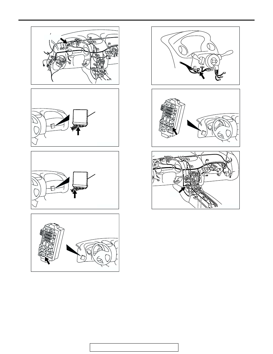
CONNECTOR: C-41
AB
C-41 (B)
AK300060
ECM
CONNECTOR: C-53 <M/T>
AH
C-53 (G)
AK300060AD
C-50 (GR)
PCM
CONNECTOR: C-50 <A/T>
AK300124
CONNECTOR: C-111
AB
C-111
AK300116
CONNECTOR: C-87
AB
C-87
AK300123
CONNECTOR: C-108
AB
C-108
AK300119
CONNECTOR: C-28
AB
C-28