Mitsubishi Eclipse. Manual - part 284


  Index      Mitsubishi     Mitsubishi Eclipse - service repair manual 2004 year


Search            


Content   ..  282  283  284  285   ..


Mitsubishi Eclipse. Manual - part 284


MULTIPORT FUEL INJECTION (MFI) DIAGNOSIS

TSB Revision

MULTIPORT FUEL INJECTION (MFI) <2.4L>

13A-629

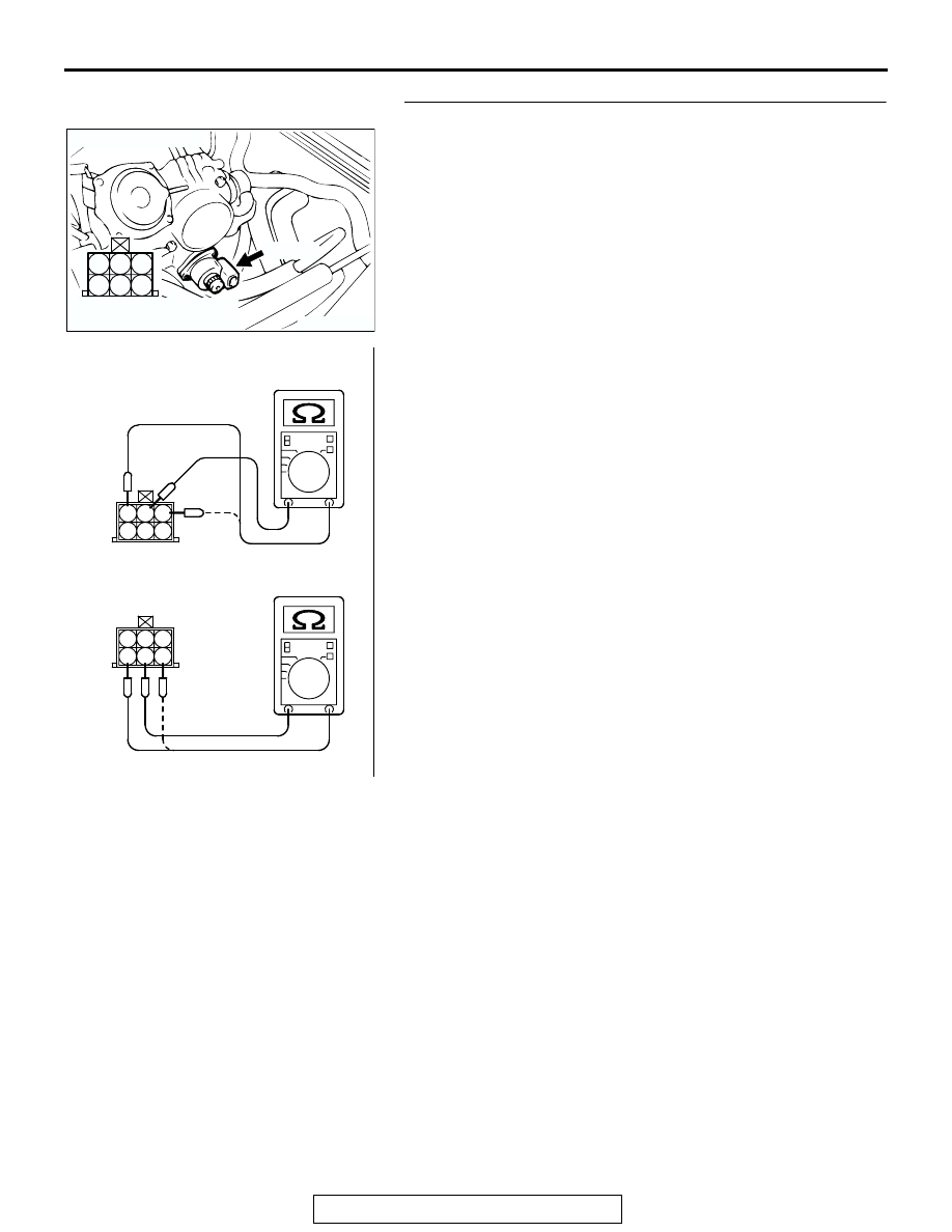
STEP 4. Check the idle air control motor coil resistance.
(1) Disconnect the idle air control motor connector B-34.

(2) Measure the resistance between idle air control motor 

connector terminal No. 2 and either terminal No. 1 or 
terminal No. 3.

Standard value: 28 

 33 ohms [at 20°C (68°F)]

(3) Measure the resistance between idle air control motor 

connector terminal No. 5 and either terminal No. 4 or 
terminal No. 6.

Standard value: 28 

 33 ohms [at 20°C (68°F)]

Q: Is the measured resistance between 28 and 33 ohms?

YES : Go to Step 5.
NO :  Replace the idle air control motor. Then go to Step 14.

AK300408

1

2

3

4

5

6

CONNECTOR: B-34

AB

B-34 (B)

HARNESS CONNECTOR:
COMPONENT SIDE

AKX01561

1 2 3
4 5 6

1 2 3
4 5 6

AB

MULTIPORT FUEL INJECTION (MFI) DIAGNOSIS

TSB Revision

MULTIPORT FUEL INJECTION (MFI) <2.4L>

13A-630

STEP 5. Measure the power supply voltage at idle air 
control motor harness side connector B-34.
(1) Disconnect the connector B-34 and measure at the harness 

side.

(2) Turn the ignition switch to the "ON" position.

(3) Measure the voltage between terminal No. 2, No. 5 and 

ground.

• Voltage should be battery positive voltage.

(4) Turn the ignition switch to the "LOCK" (OFF) position.
Q: Is battery positive voltage (approximately 12 volts) 

present?
YES : 
Go to Step 7.
NO :  Go to Step 6.

STEP 6. Check connector A-18X at MFI relay for damage.
Q: Is the connector in good condition?

YES :  Repair harness wire between MFI relay connector 

A-18X (terminal No. 4) and idle air control motor 
connector B-34 (terminal No. 2, No. 5) because of 
open circuit or short circuit to ground. Then go to Step 
14.

NO :  Repair or replace it. Refer to GROUP 00E, Harness 

Connector Inspection 

P.00E-2

. Then go to Step 14.

AK300408

1

2

3

4

5

6

CONNECTOR: B-34

AB

B-34 (B)

HARNESS CONNECTOR:
COMPONENT SIDE

AKX01428

3 2 1

A-34 HARNESS 
CONNECTOR: 
COMPONENT SIDE

AS

6 5 4

AK300454

2

1

3

4

CONNECTOR: A-18X

AB

A-18X

HARNESS CONNECTOR:
COMPONENT SIDE

MULTIPORT FUEL INJECTION (MFI) DIAGNOSIS

TSB Revision

MULTIPORT FUEL INJECTION (MFI) <2.4L>

13A-631

STEP 7. Measure the power supply voltage at ECM 
connector C-49 <M/T> or PCM connector C-50 <A/T> by 
backprobing.
(1) Do not disconnect the connector C-49 <M/T> or C-50 

<A/T>.

AK300413

1

14

4

19

5

22

6

17

8

15

9

18

7

20

16

2

21

23

26

24

25

3

10

11

12

13

CONNECTOR: C-49 <M/T>

C-49 (G)

AB

HARNESS CONNECTOR:
COMPONENT SIDE

AK300414

2

3

4

5

6

7

8

9

11

12

13

14

15

16

17

18

19

20

30

21

22

23

24

25

26

27

28

29

31

32

33

34

35

1

10

C-50 (GR)

CONNECTOR: C-50 <A/T>

AB

HARNESS CONNECTOR:
COMPONENT SIDE

MULTIPORT FUEL INJECTION (MFI) DIAGNOSIS

TSB Revision

MULTIPORT FUEL INJECTION (MFI) <2.4L>

13A-632

(2) Measure the voltage between terminal (No. 4, No. 5, No. 

17, No. 18) <M/T> or (No. 14, No. 15, No. 28, No. 29) 
<A/T> and ground by backprobing.

• The voltage is 1volt or lower for approximately 3 sec-

onds, then changes to the battery positive voltage when 
the Ignition switch is turned from the "LOCK" (OFF) 
position to the "ON" position.

(3) Turn the ignition switch to the "LOCK" (OFF) position.
Q: Is the voltage normal?

YES : Go to Step 10.
NO :  Go to Step 8.

AK000306

10

1 2 3 4 5 6 7 8 9

1112 13

141516171819 20 2122 23242526

AI

<M/T>

C-49 HARNESS 
CONNECTOR: 
HARNESS SIDE

AK000307

1

2

3 4

5 6

7 8

9 10 111213 1415 16 17 18 19 20 21 22 23

24 25

26 27 28 29

30 313233

34 35

AK

C-50 HARNESS 
CONNECTOR: 
HARNESS SIDE

<A/T>


Content   ..  282  283  284  285   ..