Mitsubishi Eclipse. Manual - part 283


  Index      Mitsubishi     Mitsubishi Eclipse - service repair manual 2004 year


Search            


Content   ..  281  282  283  284   ..


Mitsubishi Eclipse. Manual - part 283


MULTIPORT FUEL INJECTION (MFI) DIAGNOSIS

TSB Revision

MULTIPORT FUEL INJECTION (MFI) <2.4L>

13A-625

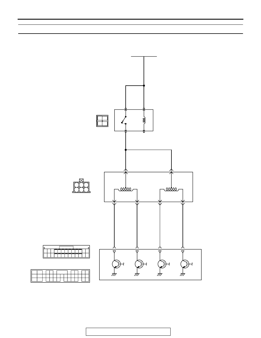
DTC P0506: Idle Control System RPM Lower Than Expected

AK101522

6

17

8

15

9

18

7

20

16

2

10

13

12

23 24 25 26

11

21

3

1

14

4

12

11

16

5 6

7 8

21

13
27

14
28

15
29

17
30

18
31

19
32

20
33

22
34

23
35

1

24

3

26

9

2

25

10

19

5

4

22

1 2
4 5 6

3

RED

-

WHITE

RED

-

WHITE

RED

-

WHITE

RED

RED

RED

GREEN-BL

ACK

GREEN-RED

GREEN-

WHITE

BL

ACK

-YELL

OW

C-49 <M/T>
(MU803773)

C-50 <A/T>
(MU803784)

B-34

IDLE AIR
CONTROL (IAC)
MOTOR

BATTERY

Idle Air Control (IAC) Motor Circuit

MFI
RELAY

1

4

2

3

3

1

2

4

5

6

ENGINE CONTROL
MODULE (ECM) <M/T>
OR
POWERTRAIN CONTROL
MODULE (PCM) <A/T>

4 <M/T>
14 <A/T>

17 <M/T>
28 <A/T>

5 <M/T>
15 <A/T>

18 <M/T>
29 <A/T>

3 4

1 2

A-18X

MULTIPORT FUEL INJECTION (MFI) DIAGNOSIS

TSB Revision

MULTIPORT FUEL INJECTION (MFI) <2.4L>

13A-626

.

CIRCUIT OPERATION

• The idle air control motor power is supplied from 

the MFI relay (terminal No. 4).

• The ECM (terminals No. 4, No. 5, No. 17, No. 18) 

<M/T> or PCM (terminals No. 14, No. 15, No. 28, 
No. 29) <A/T> drives the stepper motor by 
sequentially turning "ON" the power transistors in 
the ECM <M/T> or PCM <A/T> and providing 
ground to the idle air control motor (terminals No. 
1, No. 3, No. 4, No. 6).

.

TECHNICAL DESCRIPTION

• The amount of air taken in during idling is regu-

lated by the opening and closing of the servo 
valve located in the air passage that bypasses 
the throttle body.

• If there is a malfunction of the IAC system, the 

actual engine speed will not be identical to the 
target engine speed.

• The ECM <M/T> or PCM <A/T> checks the differ-

ence between the actual engine speed and the 
target engine speed.

.

DESCRIPTIONS OF MONITOR METHODS
Difference between actual and target idle speed is 

over the specified value.

.

MONITOR EXECUTION
Continuous

.

MONITOR EXECUTION CONDITIONS (Other 
monitor and Sensor)

Other Monitor (There is no temporary DTC stored 

in memory for the item monitored below)

• Misfire monitor

• Exhaust gas recirculation (EGR) system monitor

• Fuel system monitor

Sensor (The sensor below is determined to be 

normal)

• Volume airflow sensor

• Engine coolant temperature sensor

• Intake air temperature sensor

• Barometric pressure sensor

• Throttle position sensor

.

AK300056

CONNECTOR: B-34

AB

IDLE AIR
CONTROL MOTOR

B-34 (B)

AK300060

ECM

CONNECTOR: C-49 <M/T>

AC

C-49 (G)

AK300060AD

C-50 (GR)

PCM

CONNECTOR: C-50 <A/T>

AK300121

MFI RELAY

CONNECTOR: A-18X

AB

A-18X

MULTIPORT FUEL INJECTION (MFI) DIAGNOSIS

TSB Revision

MULTIPORT FUEL INJECTION (MFI) <2.4L>

13A-627

DTC SET CONDITIONS

Logic Flow Chart

.

Check Conditions

• Under the closed loop idle speed control.

• Engine coolant temperature is more than 77°C 

(171

°F).

• Battery positive voltage is higher than 10 volts.

• Power steering pressure switch: "OFF".

• Volumetric efficiency is lower than 40 percent.

• Barometric pressure is higher than 76 kPa (22.4 

in.Hg).

• Intake air temperature is higher than −10°C 

(14

°F).

• 25 seconds have elapsed from the start of the 

previous monitoring.

• Target idle air control motor position is more than 

100 steps.

Judgment Criteria

• The actual idle speed is more than 100 r/min 

lower than the target idle speed for 12 seconds.

.

OBD-ll DRIVE CYCLE PATTERN
Refer to Diagnostic Function 

− OBD-ll Drive Cycle − 

Procedure 6 

− Other Monitor 

P.13A-5

.

.

TROUBLESHOOTING HINTS (The most likely 
causes for this code to be set are: )

• Idle air control motor failed.

• Open or shorted idle air control motor circuit, or 

harness damage, or connector damage.

• ECM failed. <M/T>

• PCM failed. <A/T>

DIAGNOSIS

Required Special Tools:

• MB991958 (MUT-III Sub Assembly)

• MB991824: V.C.I.

END

NO

NO

NO

YES

YES

YES

MALFUNCTION

GOOD

START

CALCULATE  

Ne

MONITORING

CONDITIONS

Ne = (ACTUAL-Ne) - (TARGET-Ne)

Ne: ENGINE SPEED


Ne < -100 r/min OR

> 200 r/min

HAVE 10secs PASSED?

AK204002

MULTIPORT FUEL INJECTION (MFI) DIAGNOSIS

TSB Revision

MULTIPORT FUEL INJECTION (MFI) <2.4L>

13A-628

• MB991827: USB Cable

• MB991911: Main Harness B

• MB991709: Test harness Set

STEP 1. Using scan tool MB991958, read the diagnostic 
trouble code (DTC).

CAUTION

To prevent damage to scan tool MB991958, always turn the 
ignition switch to the "LOCK" (OFF) position before con-
necting or disconnecting scan tool MB991958.
(1) Connect scan tool MB991958 to the data link connector.
(2) Turn the ignition switch to the "ON" position.
(3) Set scan tool MB991958, read the DTC.
(4) Turn the ignition switch to the "LOCK" (OFF) position.
Q: Is the diagnostic trouble code other than P0506 output?

YES : Refer to Diagnostic Trouble Code Chart 

P.13A-24

.

NO :  Go to Step 2.

STEP 2. Check the throttle body. (throttle valve area)
Q: Is the throttle valve area dirty?

YES : Perform cleaning. Refer to, Throttle body (throttle 

valve area) cleaning 

P.13A-926

. Then go to Step 14.

NO :  Go to Step 3.

STEP 3. Check connector B-34 at idle air control motor for 
damage.
Q: Is the connector in good condition?

YES : Go to Step 4.
NO :  Repair or replace it. Refer to GROUP 00E, Harness 

Connector Inspection 

P.00E-2

. Then go to Step 14.

AK300810

AB

MB991911

16-PIN

MB991827

MB991824 

AK300408

1

2

3

4

5

6

CONNECTOR: B-34

AB

B-34 (B)

HARNESS CONNECTOR:
COMPONENT SIDE


Content   ..  281  282  283  284   ..