Mitsubishi Eclipse. Manual - part 277


  Index      Mitsubishi     Mitsubishi Eclipse - service repair manual 2004 year


Search            


Content   ..  275  276  277  278   ..


Mitsubishi Eclipse. Manual - part 277


MULTIPORT FUEL INJECTION (MFI) DIAGNOSIS

TSB Revision

MULTIPORT FUEL INJECTION (MFI) <2.4L>

13A-601

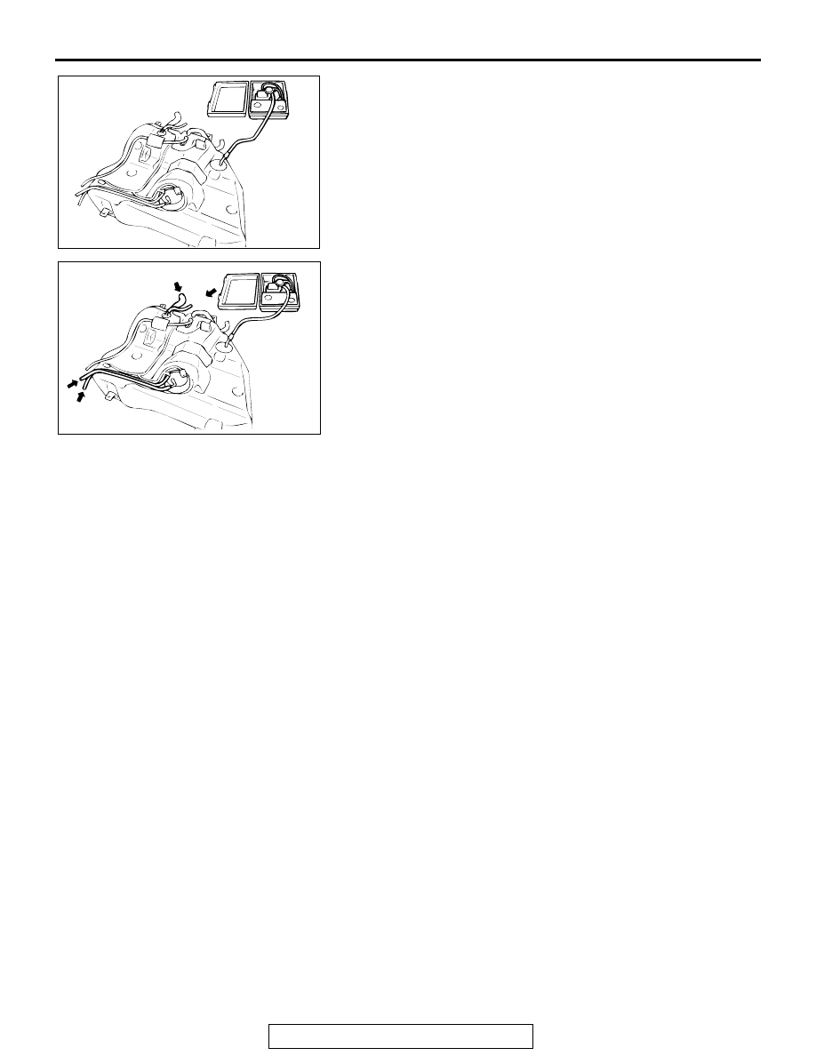
(2) Connect an evaporative emission system pressure pump to 

the leveling valve nipple.

(3) Plug the filler hose, feed pipe, return pipe and rollover valve 

nipple connected to the fuel tank.
NOTE: If these items are not securely plugged here, the 
fuel could leak in the next step.

(4) Apply pressure with the evaporative emission system 

pressure pump.

(5) In the pressurized state, check for the leak by applying soap 

water, etc. to each section.

Q: Is the fuel tank in good condition?

YES : Go to Step 17.
NO :  Replace the fuel tank, reinstall the fuel tank and fuel 

filler neck assembly. (Refer to GROUP 13C, Fuel 
Tank 

P.13C-13

.) Then go to Step 18.

AC000197

AC000198

MULTIPORT FUEL INJECTION (MFI) DIAGNOSIS

TSB Revision

MULTIPORT FUEL INJECTION (MFI) <2.4L>

13A-602

STEP 17. Using scan tool MB991958, check evaporative 
emission system monitor test.

CAUTION

• To prevent damage to scan tool MB991958, always turn 

the ignition switch to the "LOCK" (OFF) position before 
connecting or disconnecting scan tool MB991958.

• With this monitor, the ECM <M/T> or PCM <A/T> auto-

matically increases the engine speed to 1,600 r/min or 
more. Check that the transaxle is set to "neutral" <M/T> 
or "P" <A/T> position.

(1) Connect scan tool MB991958 to the data link connector.
(2) Turn the ignition switch to the "ON" position.
(3) Erase the DTCs using scan tool MB991958.
(4) Check that the fuel cap is securely closed. (Tighten until 

three clicks are heard.)

(5) Start the engine.
(6) Select "System Test," and press the "YES" key.
(7) Select "Evap Leak Mon," and press the "YES" key.
(8) During the monitor, keep the accelerator pedal at the idling 

position.
NOTE: If the engine speed does not reach 2,000 r/min dur-
ing the monitor test, adjustment of the Speed Adjusting 
Screw may be needed. Refer to 

P.13A-928

. And adjust to 

the standard value.

(9) Keep the engine speed and engine load within the specified 

range. When the monitor test starts, the "In Progress" item 
on the scan tool MB991958 will change from "NO" to "YES."

(10)Turn the ignition switch to the "LOCK" (OFF) position. Then 

disconnect scan tool MB991958.

Q: What is displayed on scan tool MB991958?

"Evap Leak Mon. Completed. Test Passed" : The 

evaporative emission system is working properly at 
this time. Then go to Step 18 .

"Evap Leak Mon. Completed. Test Failed and DTCs Set" 

Replace the ECM <M/T> or PCM <A/T>. Then go to 
Step 18.

"Evap Lead Mon. discontinued. Retest again from the 
first" : 
The monitor was discontinued for a certain reason 

(vehicle speed input from ECM <M/T> or PCM <A/T>, 
engine speed and engine load deviating from 
specified range). Turn the ignition switch to the 
"LOCK" (OFF) position once, and recheck 
evaporative emission system monitor test.

AC303127

AB

MB991911

16-PIN

MB991827

MB991824 

MULTIPORT FUEL INJECTION (MFI) DIAGNOSIS

TSB Revision

MULTIPORT FUEL INJECTION (MFI) <2.4L>

13A-603

STEP 18. Test the OBD-II drive cycle.
(1) Confirm the repair by performing the appropriate drive cycle  

(Refer to Diagnostic Function 

− OBD-ll Drive Cycle − 

Procedure 1 

− Evaporative Emission System Leak Monitor 

P.13A-5

). 

(2) Read the diagnostic trouble code.
Q: Is diagnostic trouble code P0456 set?

YES : Go to Step 1.
NO :  This diagnosis is complete.

MULTIPORT FUEL INJECTION (MFI) DIAGNOSIS

TSB Revision

MULTIPORT FUEL INJECTION (MFI) <2.4L>

13A-604

DTC P0461: Fuel Level Sensor Circuit Range/Performance

ENGINE CONTROL
MODULE (ECM) <M/T>
OR
POWERTRAIN CONTROL
MODULE (PCM) <A/T> 

FUEL GAUGE UNIT
(INTEGRATED IN FUEL PUMP MODULE)

82

78

81

80

89 90 91 92

79

87

71

74

73

72

76

75

77

85

88

83 84

86

 C-60 <M/T>
(MU803772)

Fuel Gauge Unit Circuit

13

2

1

38

BLA

C

K

GREEN-RED

42 43
48 49 50 51 52 53 54 55 56 57

46

45

44

58 59

60 61 62 63

64 65 66

47

41

 C-54 <A/T>

(MU803781)

AK101535

74 <M/T>
60 <A/T>

4

17

1

12 13 14

18

30

41

34

3

16

10

6 7

19

31

42

20

32

43

21

33

25

24

26

36

35

37

29

28

15

27

38

8 9

39 40

11

2

22

5

23

C-90

C-28

7 8

5

3 4

35

34

10 11 12

2122 23 24

13 14 15

25 26 27

16

28

17

18 19 20

29

30 31

32 33

36 37

38

9

1 2

6

1 2 3

4 5

      D-17
(MU802058)

GREEN-RED

GREEN-RED

METER AND GAUGE


Content   ..  275  276  277  278   ..