Mitsubishi Eclipse. Manual - part 272


  Index      Mitsubishi     Mitsubishi Eclipse - service repair manual 2004 year


Search            


Content   ..  270  271  272  273   ..


Mitsubishi Eclipse. Manual - part 272


MULTIPORT FUEL INJECTION (MFI) DIAGNOSIS

TSB Revision

MULTIPORT FUEL INJECTION (MFI) <2.4L>

13A-581

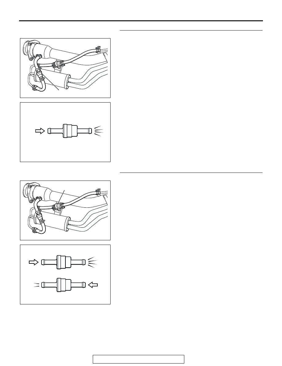
STEP 12. Check the check valve A.
(1) Only when you blow the check valve from the direction 

shown, it should pass air.

(2) When you blow the check valve, air should leak from the 

check valve body.

Q: Is check valve A in good condition?

YES : Go to Step 13.
NO :  Replace the check valve A, and reinstall the filler neck 

assembly. (Refer to GROUP 13C, Fuel Tank 

P.13C-13

.) Then go to Step 27.

STEP 13. Check the check valve B.
(1) When you blow the check valve from the arrow direction 

shown above, it should pass more air.

(2) When you blow the check valve from the arrow direction 

shown below, it should pass less air.

(3) When you blow the check valve, air should leak from the 

check valve body.

Q: Is check valve B in good condition?

YES : Go to Step 14.
NO :  Replace the check valve B, and reinstall the filler neck 

assembly. (Refer to GROUP 13C, Fuel Tank 

P.13C-13

.) Then go to Step 27.

AC002039

CHECK VALVE A

AE

AC002076 AB

CHECK VALVE A

AC002039

CHECK VALVE B

AF

AC002078

CHECK VALVE B

AB

MULTIPORT FUEL INJECTION (MFI) DIAGNOSIS

TSB Revision

MULTIPORT FUEL INJECTION (MFI) <2.4L>

13A-582

STEP 14. Check for leaks in the evaporator line from hose 
N.
(1) The leakage test with a hand vacuum pump on the hose N.
Q: Is the hose N in good condition?

YES : Go to Step 15.
NO :  Replace the hose N, and reinstall the fuel tank. (Refer 

to GROUP 13C, Fuel Tank 

P.13C-13

.) Then go to 

Step 27.

STEP 15. Check for leaks in the fuel tank.
(1) Visually check for cracks and leaks, etc.

NOTE: Carefully check the fuel pump assembly and the 
inner pressure sensor installation section in the fuel tank.

AC000195

HOSE N

AD

AC000196

MULTIPORT FUEL INJECTION (MFI) DIAGNOSIS

TSB Revision

MULTIPORT FUEL INJECTION (MFI) <2.4L>

13A-583

(2) Connect an evaporative emission system pressure pump to 

the leveling valve nipple.

(3) Plug the filler hose, feed pipe, return pipe and rollover valve 

nipple connected to the fuel tank.
NOTE: If these items are not securely plugged here, the 
fuel could leak in the next step.

(4) Apply pressure with the evaporative emission system 

pressure pump.

(5) In the pressurized state, check for the leak by applying soap 

water, etc. to each section.

Q: Are there any leaks?

There are leaks at the fuel pump module or the fuel tank 
differential pressure sensor section. : 
After reassemble 

the leaked parts, check again that there are no leaks. 
Then reinstall the fuel tank. (Refer to GROUP 13C, 
Fuel Tank 

P.13C-13

.) Then go to Step 27.

There are leaks at the fuel tank. : Replace the fuel tank, 

reinstall the fuel tank. (Refer to GROUP 13C, Fuel 
Tank 

P.13C-13

.) Then go to Step 27.

There are no leaks. : Then go to Step 16.

STEP 16. Visually check for cracks in the fuel tank filler 
neck.
(1) Visually check for cracks in the fuel tank filler neck.
Q: Is the fuel filler neck assembly in good condition?

YES : Reinstall the fuel tank and fuel filler neck assembly. 

(Refer to GROUP 13C, Fuel Tank 

P.13C-13

.) Then go 

to Step 27.

NO :  Replace the fuel tank filler neck assembly and 

reinstall the fuel tank. (Refer to GROUP 13C, Fuel 
Tank 

P.13C-13

.) Then go to Step 27.

AC000197

AC000198

MULTIPORT FUEL INJECTION (MFI) DIAGNOSIS

TSB Revision

MULTIPORT FUEL INJECTION (MFI) <2.4L>

13A-584

STEP17. Pressure test for clogging in the evaporator line 
from hose G to hose N.
(1) Disconnect hose G from the evaporative emission canister 

side, and unplug the hose G.

(2) On the EVAP pressure pump, set the pressure/hold valve to 

OPEN, and set the vent valve to CLOSED. Turn the pump 
timer to ON. You can reset the timer as required. (These 
settings are listed under "Leak Test" in the pump 
instructions.)

(3) Air should pass through hose G.
Q: Is air blown from hose G?

YES : Connect the hose G. Then go to Step 18.
NO :  Go to Step 22.

STEP18. Pressure test for clogging in the evaporator line 
from hose D to hose F.
(1) Unplug hose E.
(2) On the EVAP pressure pump, set the pressure/hold valve to 

OPEN, and set the vent valve to CLOSED. Turn the pump 
timer to ON. You can reset the timer as required. (These 
settings are listed under "Leak Test" in the pump 
instructions.)

(3) Air should pass through hose E.
Q: Is air blown from hose E?

YES : Connect the hose E. Then go to Step 19.
NO :  Go to Step 20.

AC002036 AC

HOSE G

OPEN

OPEN

CLOSED

CLOSED

Pressure
   Hold

Vent

ACX01806

OPEN

OPEN

CLOSED

CLOSED

Pressure
   Hold

Vent

ACX01806

AC002029

HOSE E

AC


Content   ..  270  271  272  273   ..