Mitsubishi Eclipse. Manual - part 271


  Index      Mitsubishi     Mitsubishi Eclipse - service repair manual 2004 year


Search            


Content   ..  269  270  271  272   ..


Mitsubishi Eclipse. Manual - part 271


MULTIPORT FUEL INJECTION (MFI) DIAGNOSIS

TSB Revision

MULTIPORT FUEL INJECTION (MFI) <2.4L>

13A-577

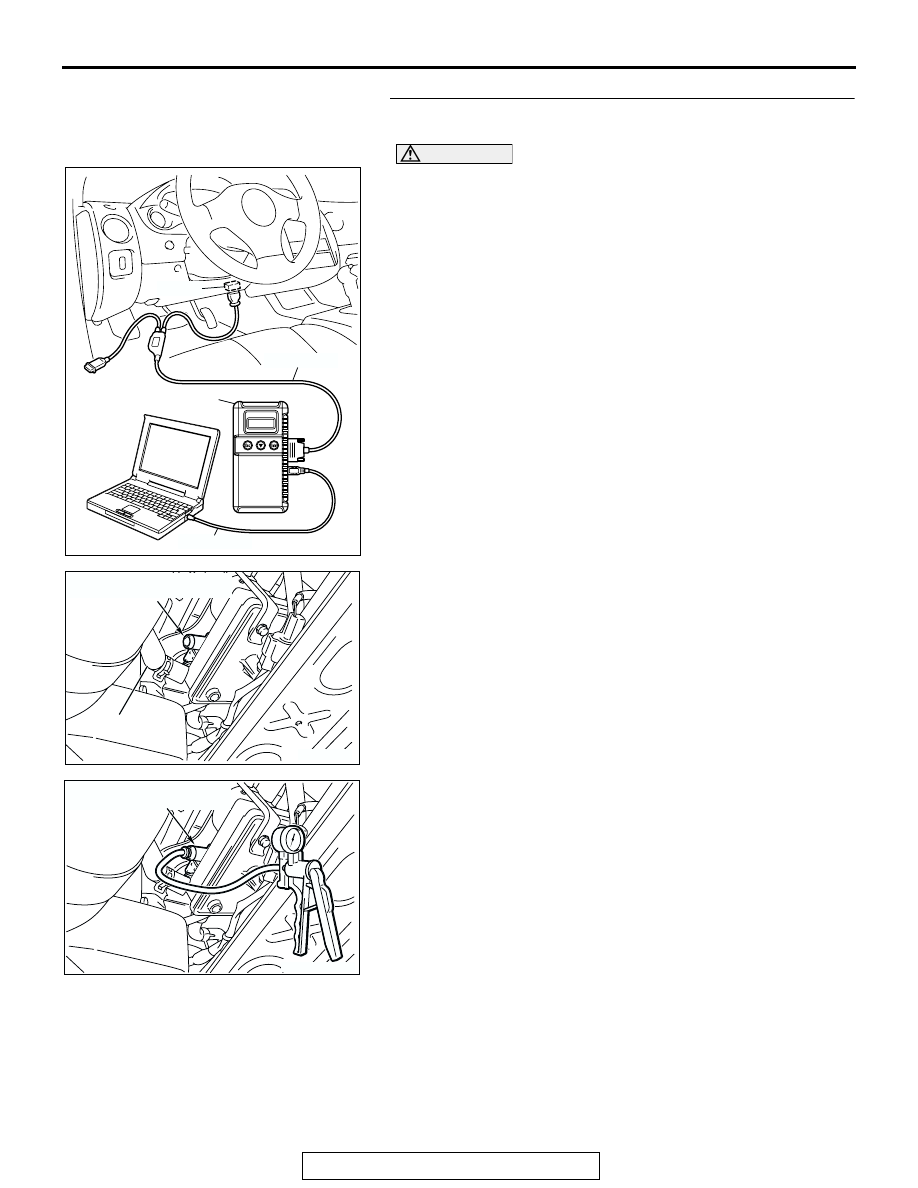
STEP 5. Check the evaporative emission ventilation 
solenoid using scan tool MB991958.

CAUTION

To prevent damage to scan tool MB991958, always turn the 
ignition switch to the "LOCK" (OFF) position before con-
necting or disconnecting scan tool MB991958.
(1) Connect scan tool MB991958 to the data link connector.

(2) Disconnect hose E from the evaporative emission 

ventilation solenoid side, and connect a hand vacuum 
pump.

(3) Turn the ignition switch to the "ON" position.
(4) Set scan tool MB991958 to actuator test mode for item 29: 

Evaporative Emission Ventilation Solenoid. When the 
evaporative emission ventilation solenoid is operated, apply 
a pressure on the hand vacuum pump and confirm that air 
is maintained.

(5) Turn the ignition switch to the "LOCK" (OFF) position. Then 

disconnect scan tool MB991958.

(6) Disconnect the hand vacuum pump, and connect hose E to 

the evaporative emission canister.

Q: Is the solenoid valve in good condition?

YES : Go to Step 6.
NO :  Replace the evaporative emission ventilation 

solenoid. Then go to Step 27.

AC303127

AB

MB991911

16-PIN

MB991827

MB991824 

AC002030

EVAPORATIVE EMISSION 

VENTILATION SOLENOID

HOSE E

AC

AC002031AB

EVAPORATIVE EMISSION 

VENTILATION SOLENOID

MULTIPORT FUEL INJECTION (MFI) DIAGNOSIS

TSB Revision

MULTIPORT FUEL INJECTION (MFI) <2.4L>

13A-578

STEP 6. Pressure test for leaks in the evaporator line from 
hose D to hose N.
(1) Disconnect hose E from the evaporative emission 

ventilation solenoid side, and plug the hoses.

(2) Remove the fuel cap.

(3) Connect the evaporative emission system pressure pump 

to the fuel filler neck.

(4) Apply a pressure on the evaporative emission system 

pressure pump, and confirm that air is maintained.
NOTE: "Pressure test" in this procedure refers to the 
I/M240 Simulation Test (8 simple steps) described in the 
evaporative emission system pressure pump (Miller number 
6872A) manufacture's instructions located in the lid of the 
pump box.

(5) Disconnect the evaporative emission system pressure 

pump, and reinstall the fuel cap.

(6) Connect hose E to the evaporator line.
Q: Is air maintained?

YES : Go to Step 17.
NO :  Go to Step 7.

STEP 7. Pressure test for leaks in the evaporator line from 
hose G to hose N.
(1) Disconnect hose G from the evaporative emission canister 

side, and plug the hose.

(2) Perform the pressure test again.
Q: Is air maintained?

YES : Go to Step 10.
NO :  Go to Step 8.

AC002028

HOSE E

AC

AC000186

AC002036 AC

HOSE G

MULTIPORT FUEL INJECTION (MFI) DIAGNOSIS

TSB Revision

MULTIPORT FUEL INJECTION (MFI) <2.4L>

13A-579

STEP 8. Check for leaks in the evaporator line from hose D 
to hose F.
(1) Remove the fuel tank. (Refer to GROUP 13C, Fuel Tank 

P.13C-13

.)

(2) The leakage test with a hand vacuum pump on each hose 

from hose D to hose F.

Q: Are the hoses in good condition?

YES : Go to Step 9.
NO :  Replace the inferior hose, and reinstall the fuel tank. 

(Refer to GROUP 13C, Fuel Tank 

P.13C-13

.) Then go 

to Step 27.

STEP 9. Check for leaks in the evaporative emission 
canister.
(1) Connect a hand vacuum pump to the vent nipple of the 

evaporative emission canister.

(2) Plug the other two nipples or loop a hose between the other 

nipples.

(3) Apply a vacuum with the hand vacuum pump, and confirm 

that air is maintained.

Q: Is the evaporative emission canister in good condition?

YES : Go to Step 27.
NO :  Replace the evaporative emission canister (Refer to 

GROUP 17, Evaporative Emission Canister and Fuel 
Tank Pressure Relief Valve 

P.17-117

,) and reinstall 

the fuel tank. (Refer to GROUP 13C, Fuel Tank 

P.13C-13

.) Then go to Step 27.

AC002037AE

HOSE D

HOSE F

HOSE E

AC000191AB

VENT
NIPPLE

MULTIPORT FUEL INJECTION (MFI) DIAGNOSIS

TSB Revision

MULTIPORT FUEL INJECTION (MFI) <2.4L>

13A-580

STEP 10. Check for leaks in the evaporator line from hose 
H to hose I.
(1) Remove the fuel tank. (Refer to GROUP 13C, Fuel Tank 

P.13C-13

.)

(2) Disconnect hose H at the liquid separator side, and then 

connect a hand vacuum pump to the hose.

(3) Plug the hose I at the fuel tank side.
(4) Apply vacuum by using the hand vacuum pump, and 

confirm that the applied vacuum does not fluctuate.

Q: Is air maintained?

YES : Go to Step 11.
NO :  Replace the inferior hose, and reinstall the fuel tank. 

(Refer to GROUP 13C, Fuel Tank 

P.13C-13

.) Then go 

to Step 27.

STEP 11. Check for leaks in the evaporator line hose G, J, 
K, L and hose M.
(1) Remove the filler neck assembly. (Refer to GROUP 13C, 

Fuel Tank 

P.13C-13

.)

(2) The leakage test with a hand vacuum pump on each hose 

from hoses G, J, K, L and M.

Q: Are the hoses in good condition?

YES : Go to Step 12.
NO :  Replace the inferior hose, and reinstall the filler neck 

assembly. (Refer to GROUP 13C, Fuel Tank 

P.13C-13

.) Then go to Step 27.

AC02040 AC

HOSE H

AC002038

HOSE I

AC

AC002032

AB

HOSE G

AC

AC002039

AB

HOSE L

AC

HOSE K

HOSE M

HOSE J


Content   ..  269  270  271  272   ..