Mitsubishi Eclipse. Manual - part 265
MULTIPORT FUEL INJECTION (MFI) DIAGNOSIS
TSB Revision
MULTIPORT FUEL INJECTION (MFI) <2.4L>
13A-553
STEP 22. Test the OBD-II drive cycle.
(1) Carry out a test drive with the drive cycle pattern (Refer to
Diagnostic Function
− OBD-ll Drive Cycle − Procedure 1 −
Evaporative Emission System Leak Monitor
(2) Read the diagnostic trouble code.
Q: Is diagnostic trouble code P0452 set?
YES : Go to Step 2.
NO : This diagnosis is complete.
DTC P0453: Evaporative Emission Control System Pressure Sensor High Input
AC001943
A
B
C
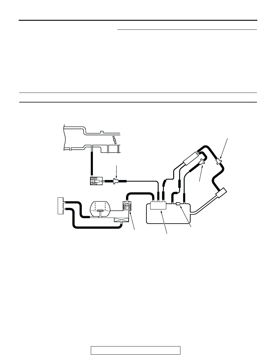
EVAPORATIVE EMISSION
PURGE SOLENOID
EVAPORATIVE
EMISSION CANISTER
EVAPORATIVE
EMISSION
VENTILATION
SOLENOID
FUEL TANK
CHECK VALVE A
CHECK
VALVE B
INTAKE MANIFOLD
SYSTEM DIAGRAM
D
E
F
G
I
H
L
N
M
K
J
O
P
CHAMBER
AC
FUEL TANK DIFFRENTIAL
PRESSURE SENSOR