Mitsubishi Eclipse. Manual - part 264


  Index      Mitsubishi     Mitsubishi Eclipse - service repair manual 2004 year


Search            


Content   ..  262  263  264  265   ..


Mitsubishi Eclipse. Manual - part 264


MULTIPORT FUEL INJECTION (MFI) DIAGNOSIS

TSB Revision

MULTIPORT FUEL INJECTION (MFI) <2.4L>

13A-549

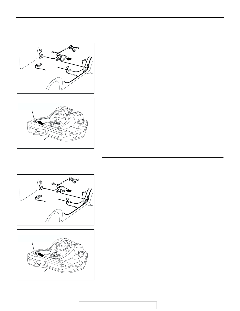
STEP 15. Check connectors D-16 at intermediate 
connector and D-18 at fuel tank differential pressure 
sensor for damage.
Q: Are the connectors in good condition?

YES : Go to Step 16.
NO :  Repair or replace it. Refer to GROUP 00E, Harness 

Connector Inspection 

P.00E-2

. Then go to Step 22.

STEP 16. Check the harness wire between intermediate 
connector D-16 terminal 8 and fuel tank differential 
pressure sensor connector D-18 terminal 3 for damage.
Q: Is the harness wire in good condition?

YES : Go to Step 17.
NO :  Repair it. Then go to 22.

AC001787AD

CONNECTOR: D-16

AC103356

FUEL TANK

AD

CONNECTOR: D-18
FUEL TANK DIFFERENTIAL 
PRESSURE SENSOR

AC001787AD

CONNECTOR: D-16

AC103356

FUEL TANK

AD

CONNECTOR: D-18
FUEL TANK DIFFERENTIAL 
PRESSURE SENSOR

MULTIPORT FUEL INJECTION (MFI) DIAGNOSIS

TSB Revision

MULTIPORT FUEL INJECTION (MFI) <2.4L>

13A-550

STEP 17. Check the harness wire between intermediate 
connector D-16 terminal 6 and fuel tank differential 
pressure sensor connector D-18 terminal 2 for damage.
Q: Is the harness wire in good condition?

YES : Replace the fuel tank differential pressure sensor. 

Then go to 22.

NO :  Repair it. Then go to 22.

STEP 18. Check the output circuit voltage at fuel tank 
differential pressure sensor connector D-18. 
(1) Remove the center exhaust pipe. (Refer to GROUP 15, 

Exhaust Pipe, Main Muffler and Catalytic Converter 

P.15-22

.)

(2) Remove the fuel band assembly, tilt the fuel tank.
(3) Disconnect fuel tank differential pressure sensor connector 

D-18.

(4) Use special tool (MB991658) to connect terminals 1, 2 and 

3 of the disconnected sensor connector and those of the 
harness side connector respectively.

(5) Turn the ignition switch to the "ON" position.
(6) Remove the fuel cap.
(7) Measure the voltage between terminal 1 and ground.

• Voltage should be between 2.0 and 3.0 volts.

(8) Turn the ignition switch to the "LOCK" (OFF) position.
Q: Is the voltage normal?

YES : Remove the special tool and connect fuel tank 

differential pressure sensor connector D-18. Then go 
to Step 19.

NO :  Replace the fuel tank differential pressure sensor. 

Then go to 22.

AC001787AD

CONNECTOR: D-16

AC103356

FUEL TANK

AD

CONNECTOR: D-18
FUEL TANK DIFFERENTIAL 
PRESSURE SENSOR

AC002081AB

MB991658

FUEL TANK DIFFERENTIAL 
PRESSURE SENSOR

MULTIPORT FUEL INJECTION (MFI) DIAGNOSIS

TSB Revision

MULTIPORT FUEL INJECTION (MFI) <2.4L>

13A-551

STEP 19. Check connectors D-16 at intermediate 
connector and D-18 at fuel tank differential pressure 
sensor for damage.
Q: Are the connectors in good condition?

YES : Go to Step 20.
NO :  Repair or replace it. Refer to GROUP 00E, Harness 

Connector Inspection 

P.00E-2

. Then go to Step 22.

STEP 20. Check the harness wire between intermediate 
connector D-16 terminal 5 and fuel tank differential 
pressure sensor connector D-18 terminal 1 for damage.
Q: Is the harness wire in good condition?

YES : Go to Step 22.
NO :  Repair it. Then go to 22.

AC001787AD

CONNECTOR: D-16

AC103356

FUEL TANK

AD

CONNECTOR: D-18
FUEL TANK DIFFERENTIAL 
PRESSURE SENSOR

AC001787AD

CONNECTOR: D-16

AC103356

FUEL TANK

AD

CONNECTOR: D-18
FUEL TANK DIFFERENTIAL 
PRESSURE SENSOR

MULTIPORT FUEL INJECTION (MFI) DIAGNOSIS

TSB Revision

MULTIPORT FUEL INJECTION (MFI) <2.4L>

13A-552

STEP 21. Using scan tool MB991958, check data list item 
73: Fuel Tank Differential Pressure Sensor.

CAUTION

To prevent damage to scan tool MB991958, always turn the 
ignition switch to the "LOCK" (OFF) position before con-
necting or disconnecting scan tool MB991958.
(1) Connect scan tool MB991958 to the data link connector.

(2) Disconnect hose G from the evaporative emission canister 

side, and plug the hose from which the pipes have been 
disconnected.

(3) Turn the ignition switch to the "ON" position.
(4) Remove the fuel cap.
(5) Set scan tool MB991958 to the data reading mode for item 

73, Fuel Tank Differential Pressure Sensor.

• The fuel tank pressures should be −1.5 to 1.5  kPa 

(

−0.443 to 0.443 inHg.)

(6) Connect an evaporative emission system pressure pump to 

the fuel filler neck, and apply pressure.

• The scan tool reading should increase.

(7) Turn the ignition switch to the "LOCK" (OFF) position. Then 

disconnect scan tool MB991958.

Q: Is the scan tool reading within the specified value?

YES : This malfunction is intermittent malfunction. Refer to 

GROUP 00, How to Use Troubleshooting/Inspection 
Service Points 

P.00-6

. Then go to Step 22.

NO :  Replace the ECM <M/T> or PCM <A/T>. Then go to 

Step 22.

AC303127

AB

MB991911

16-PIN

MB991827

MB991824 

AC002036 AC

HOSE G

AC000186


Content   ..  262  263  264  265   ..