Mitsubishi Eclipse. Manual - part 258


  Index      Mitsubishi     Mitsubishi Eclipse - service repair manual 2004 year


Search            


Content   ..  256  257  258  259   ..


Mitsubishi Eclipse. Manual - part 258


MULTIPORT FUEL INJECTION (MFI) DIAGNOSIS

TSB Revision

MULTIPORT FUEL INJECTION (MFI) <2.4L>

13A-525

STEP 5. Check the harness wire between ECM connector 
C-56 terminal 61 <M/T> or PCM connector C-57 terminal 92 
<A/T> and intermediate connector D-16 terminal 5 for 
damage.
Q: Is the harness wire in good condition?

YES : Go to Step 22.
NO :  Repair it. Then go to 22.

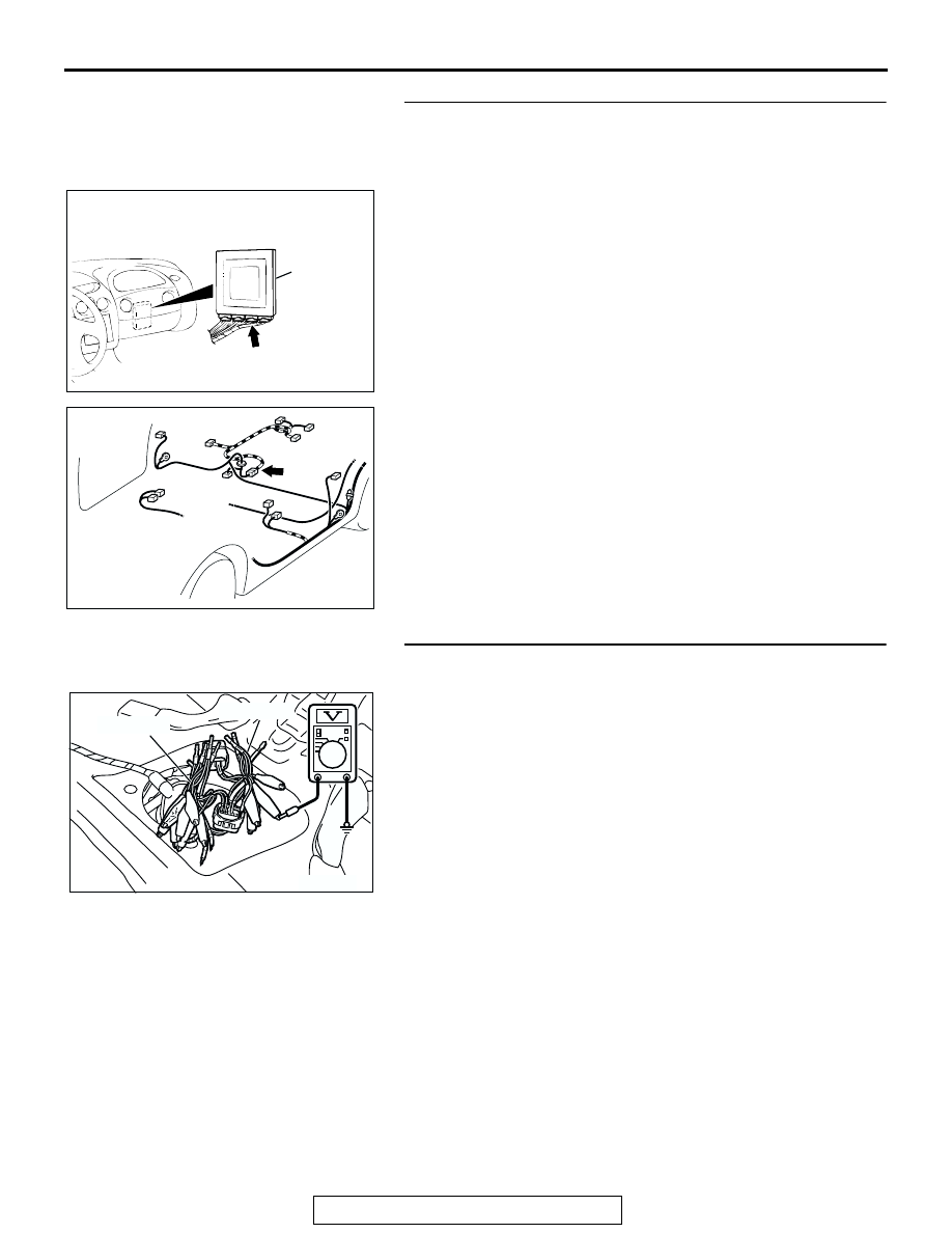
STEP 6. Check the 5-volt supply circuit voltage at 
intermediate connector D-16.
(1) Use special tools (MB991658 and MB991709) to connect 

terminals 5, 6 and 8 between connectors of the 
intermediate connector D-16 respectively.

(2) Turn the ignition switch to the "ON" position.
(3) Measure the voltage between terminal 8 and ground.

• Voltage should be between 4.9 and 5.1 volts.

(4) Turn the ignition switch to the "LOCK" (OFF) position.
Q: Is the voltage normal?

YES : Go to Step 11.
NO :  Remove the special tools and connect intermediate 

connector D-16. Then go to Step 7.

AC001689

CONNECTOR: C-56 <M/T>, C-57 <A/T>

ECM <M/T>
OR
PCM <A/T>

C-56 <M/T>, 
C-57 <A/T>

AM

AC001787AD

CONNECTOR: D-16

AC002080

MB991709

MB991658

AB

MULTIPORT FUEL INJECTION (MFI) DIAGNOSIS

TSB Revision

MULTIPORT FUEL INJECTION (MFI) <2.4L>

13A-526

STEP 7. Check the 5-volt supply circuit voltage at ECM 
connector C-60 <M/T> or PCM connector C-54 <A/T> by 
backprobing.
(1) Do not disconnect ECM connector C-60 <M/T> or PCM 

connector C-54 <A/T>.

(2) Turn the ignition switch to the "ON" position.
(3) Measure the voltage between terminal 81 <M/T> or terminal 

46 <A/T> and ground by backprobing.

• Voltage should be between 4.9 and 5.1 volts.

(4) Turn the ignition switch to the "LOCK" (OFF) position.
Q: Is the voltage normal?

YES : Go to Step 9.
NO :  Go to Step 8.

STEP 8. Check connector C-60 at ECM <M/T> or C-54 at 
PCM <A/T> for damage.
Q: Is the connector in good condition?

YES : Go to Step 21.
NO :  Repair or replace it. Refer to GROUP 00E, Harness 

Connector Inspection 

P.00E-2

. Then go to Step 22.

AC002552

HARNESS SIDE 
CONNECTOR

<M/T> C-60

<A/T> C-54

AC

AC001689

CONNECTOR: C-60 <M/T>, C-54 <A/T>

ECM <M/T>
OR
PCM <A/T>

AL

C-54 
<A/T>

C-60 
<M/T>

MULTIPORT FUEL INJECTION (MFI) DIAGNOSIS

TSB Revision

MULTIPORT FUEL INJECTION (MFI) <2.4L>

13A-527

STEP 9. Check connectors C-28, C-90, D-16 at intermediate 
connector for damage.
Q: Are the connectors in good condition?

YES : Go to Step 10.
NO :  Repair or replace it. Refer to GROUP 00E, Harness 

Connector Inspection 

P.00E-2

. Then go to Step 22.

AC001741 AJ

CONNECTOR: C-28

AC001991

CONNECTOR: C-90

CONNECTOR
BLOCK (LH)

AI

AC001787AD

CONNECTOR: D-16

MULTIPORT FUEL INJECTION (MFI) DIAGNOSIS

TSB Revision

MULTIPORT FUEL INJECTION (MFI) <2.4L>

13A-528

STEP 10. Check the harness wire between ECM connector 
C-60 terminal 81 <M/T> or PCM connector C-54 terminal 46 
<A/T> and intermediate connector D-16 terminal 8 for 
damage.
Q: Is the harness wire in good condition?

YES : Go to Step 22.
NO :  Repair it. Then go to 22.

STEP 11. Check the circuit voltage at intermediate 
connector D-16. 
(1) Use special tools (MB991658 and MB991709) to connect 

terminals 5 and 8 between connectors of the intermediate 
connector D-16 respectively.

(2) Turn the ignition switch to the "ON" position.

(3) Measure the voltage at the male side connector between 

terminal 6 and ground.

• The voltage should be 0.5 volt or less.

(4) Turn the ignition switch to the "LOCK" (OFF) position.
(5) Remove the special tools and connect intermediate 

connector D-16.

Q: Is the voltage normal?

YES : Go to Step 12.
NO :  Go to Step 15.

AC001689

CONNECTOR: C-60 <M/T>, C-54 <A/T>

ECM <M/T>
OR
PCM <A/T>

AL

C-54 
<A/T>

C-60 
<M/T>

AC001787AD

CONNECTOR: D-16

AC106525

AB

MB991709

MB991658

INTERMEDIATE 
CONNECTOR D-16

INTERMEDIATE 
CONNECTOR D-16

AC106528

1

2 3 4 5 6

7

8

9

10

AB

INTERMEDIATE 
CONNECTOR D-16
MALE SIDE 
CONNECTOR


Content   ..  256  257  258  259   ..