Mitsubishi Eclipse. Manual - part 226


  Index      Mitsubishi     Mitsubishi Eclipse - service repair manual 2004 year


Search            


Content   ..  224  225  226  227   ..


Mitsubishi Eclipse. Manual - part 226


MULTIPORT FUEL INJECTION (MFI) DIAGNOSIS

TSB Revision

MULTIPORT FUEL INJECTION (MFI) <2.4L>

13A-397

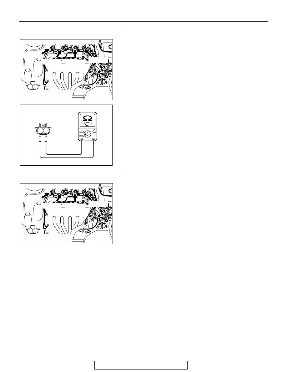
STEP 3. Check the injector.
(1) Disconnect the injector connector B-01 <No. 1 cylinder>, 

B-02 <No. 2 cylinder>, B-05 <No. 3 cylinder>, B-06 <No. 4 
cylinder>.

(2) Measure the resistance between injector side connector 

terminal No. 1 and No. 2.

Standard value: 13 

 16 ohms [at 20°C (68°F)]

Q: Is the resistance between 13 and 16 ohms?

YES : Go to Step 4.
NO :  Replace the injector. Then go to Step 9.

STEP 4. Check connector at injector for damage.

a. Check the connector B-01 when checking No. 1 cylinder.
b. Check the connector B-02 when checking No. 2 cylinder.

c. Check the connector B-05 when checking No. 3 cylinder.

d. Check the connector B-06 when checking No. 4 cylinder.

Q: Is the connector in good condition?

YES : Go to Step 5.
NO :  Repair or replace the injector. Refer to GROUP 00E, 

Harness Connector Inspection 

P.00E-2

. Then go to 

Step 9.

AK300737

1

2

CONNECTORS: B-01, B-02, B-05, B-06

AB

B-02 (GR)

B-01 (GR)

B-05 (GR)

B-06 (GR)

HARNESS CONNECTOR:
COMPONENT SIDE

AK000559

2

1

INJECTOR SIDE
CONNECTOR

AB

AK300737

1

2

CONNECTORS: B-01, B-02, B-05, B-06

AB

B-02 (GR)

B-01 (GR)

B-05 (GR)

B-06 (GR)

HARNESS CONNECTOR:
COMPONENT SIDE

MULTIPORT FUEL INJECTION (MFI) DIAGNOSIS

TSB Revision

MULTIPORT FUEL INJECTION (MFI) <2.4L>

13A-398

STEP 5. Check connector C-49 at ECM <M/T> or connector 
C-50 at PCM <A/T> for damage.
Q: Is the connector in good condition?

YES : Go to Step 6.
NO :  Repair or replace it. Refer to GROUP 00E, Harness 

Connector Inspection 

P.00E-2

. Then go to Step 9.

AK300413

1

14

4

19

5

22

6

17

8

15

9

18

7

20

16

2

21

23

26

24

25

3

10

11

12

13

CONNECTOR: C-49 <M/T>

C-49 (G)

AB

HARNESS CONNECTOR:
COMPONENT SIDE

AK300414

2

3

4

5

6

7

8

9

11

12

13

14

15

16

17

18

19

20

30

21

22

23

24

25

26

27

28

29

31

32

33

34

35

1

10

C-50 (GR)

CONNECTOR: C-50 <A/T>

AB

HARNESS CONNECTOR:
COMPONENT SIDE

MULTIPORT FUEL INJECTION (MFI) DIAGNOSIS

TSB Revision

MULTIPORT FUEL INJECTION (MFI) <2.4L>

13A-399

STEP 6. Check for harness damage between injector 
connector and ECM connector <M/T> or PCM connector 
<A/T>.

a. Check the harness wire between injector connector B-01 

(terminal No. 2) and ECM connector C-49 (terminal No. 1) 
<M/T> or PCM connector C-50 (terminal No. 1) <A/T> when 
checking No. 1 cylinder.

b. Check the harness wire between injector connector B-02 

(terminal No. 2) and ECM connector C-49 (terminal No. 14) 
<M/T> or PCM connector C-50 (terminal No. 9) <A/T> when 
checking No. 2 cylinder.

c. Check the harness wire between injector connector B-05 

(terminal No. 2) and ECM connector C-49 (terminal No. 2) 
<M/T> or PCM connector C-50 (terminal No. 24) <A/T> 
when checking No. 3 cylinder.

d. Check the harness wire between injector connector B-06 

(terminal No. 2) and ECM connector C-49 (terminal No. 15) 
<M/T> or PCM connector C-50 (terminal No. 2) <A/T> when 
checking No. 4 cylinder.

Q: Is the harness wire in good condition?

YES : Go to Step 7.
NO :  Repair it. Then go to Step 9.

STEP 7. Check the compression.
Refer to GROUP 11A, On-Vehicle Service 

− Compression 

Pressure Check 

P.11A-10

.

Q: Are there any abnormalities?

YES : Go to Step 8.
NO :  Repair or replace it. Then go to Step 9.

AK300737

1

2

CONNECTORS: B-01, B-02, B-05, B-06

AB

B-02 (GR)

B-01 (GR)

B-05 (GR)

B-06 (GR)

HARNESS CONNECTOR:
COMPONENT SIDE

AK300413

1

14

4

19

5

22

6

17

8

15

9

18

7

20

16

2

21

23

26

24

25

3

10

11

12

13

CONNECTOR: C-49 <M/T>

C-49 (G)

AB

HARNESS CONNECTOR:
COMPONENT SIDE

AK300414

2

3

4

5

6

7

8

9

11

12

13

14

15

16

17

18

19

20

30

21

22

23

24

25

26

27

28

29

31

32

33

34

35

1

10

C-50 (GR)

CONNECTOR: C-50 <A/T>

AB

HARNESS CONNECTOR:
COMPONENT SIDE

MULTIPORT FUEL INJECTION (MFI) DIAGNOSIS

TSB Revision

MULTIPORT FUEL INJECTION (MFI) <2.4L>

13A-400

STEP 8. Replace the injector.
(1) Replace the injector.
(2) Carry out a test drive with the drive cycle pattern. Refer to 

Diagnostic Function 

− OBD-II Drive Cycle − Procedure 6 − 

Other Monitor 

P.13A-5

.

(3) Check the diagnostic trouble code (DTC).
Q: Are DTC P0301, P0302, P0303 and P0304 set?

YES : Replace the ECM or PCM. Then go to Step 9.
NO :  The inspection is complete.

STEP 9. Test the OBD-II drive cycle.
(1) Carry out a test drive with the drive cycle pattern. Refer to, 

Procedure 6 

− Other Monitor 

P.13A-5

.

(2) Check the diagnostic trouble code (DTC).
Q: Are DTC P0301, P0302, P0303 and P0304 set?

YES : Retry the troubleshooting.
NO :  The inspection is complete.

AK300737

1

2

CONNECTORS: B-01, B-02, B-05, B-06

AB

B-02 (GR)

B-01 (GR)

B-05 (GR)

B-06 (GR)

HARNESS CONNECTOR:
COMPONENT SIDE


Content   ..  224  225  226  227   ..