Mitsubishi Eclipse. Manual - part 211
MULTIPORT FUEL INJECTION (MFI) DIAGNOSIS
TSB Revision
MULTIPORT FUEL INJECTION (MFI) <2.4L>
13A-337
STEP 12. Check for entry of foreign matter (water,
kerosene, etc.) into fuel.
Q: Are there any abnormalities?
YES : Go to Step 13.
NO : Replace the fuel. Then go to Step 14.
STEP 13. Replace the injector.
(1) Replace the injector.
(2) Carry out a test drive with the drive cycle pattern. Refer to
Diagnostic Function
− OBD-II Drive Cycle − Procedure 2 −
Fuel Trim Monitor
(3) Check the diagnostic trouble code (DTC).
Q: Is DTC P0171 set?
YES : Replace the ECM or PCM. Then go to Step 14.
NO : The inspection is complete.
STEP 14. Test the OBD-II drive cycle.
(1) Carry out a test drive with the drive cycle pattern. Refer to
Diagnostic Function
− OBD-II Drive Cycle − Procedure 2 −
Fuel Trim Monitor
(2) Check the diagnostic trouble code (DTC).
Q: Is DTC P0171 set?
YES : Retry the troubleshooting.
NO : The inspection is complete.
DTC P0172: System too Rich
.
System too Rich Circuit
• Refer to, DTC P0201 − P0204 Injector Circuit
Malfunction
.
CIRCUIT OPERATION
• Refer to, DTC P0201 − P0204 Injector Circuit
Malfunction
.
TECHNICAL DESCRIPTION
• If a malfunction occurs in the fuel system, the fuel
trim value becomes too small.
• The ECM <M/T> or PCM <A/T> checks whether
the fuel trim value is within a specified range.
.
DESCRIPTIONS OF MONITOR METHODS
Air/fuel learning value (long term fuel trim) and
air/fuel feedback integral value (short term fuel
trim) are too rich.
.
MONITOR EXECUTION
Continuous
.
MONITOR EXECUTION CONDITIONS (Other
monitor and Sensor)
Other Monitor (There is no temporary DTC stored
in memory for the item monitored below)
• Misfire monitor
Sensor (The sensor below is determined to be
normal)
• Volume airflow sensor
• Engine coolant temperature sensor
• Intake air temperature sensor
• Barometric pressure sensor
• Throttle position sensor
.
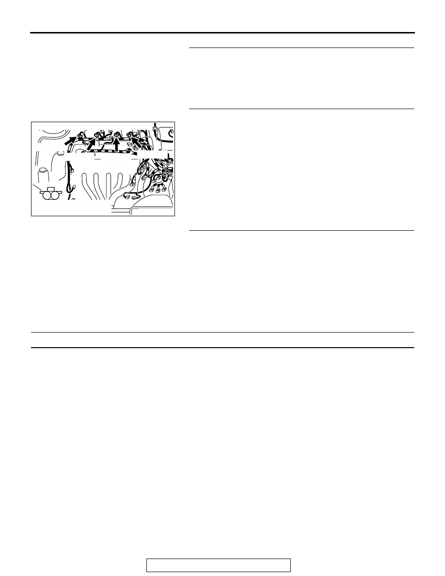
AK300737
1
2
CONNECTORS: B-01, B-02, B-05, B-06
AB
B-02 (GR)
B-01 (GR)
B-05 (GR)
B-06 (GR)
HARNESS CONNECTOR:
COMPONENT SIDE