Mitsubishi Eclipse. Manual - part 204
MULTIPORT FUEL INJECTION (MFI) DIAGNOSIS
TSB Revision
MULTIPORT FUEL INJECTION (MFI) <2.4L>
13A-309
.
CIRCUIT OPERATION
• A voltage corresponding to the oxygen concen-
tration in the exhaust gas is sent to the ECM (ter-
minal No. 75) <M/T> or PCM (terminal No. 73)
<A/T> from the output terminal (terminal No. 3) of
the heated oxygen sensor (rear).
• Terminal No. 4 of the heated oxygen sensor
(rear) is grounded with ECM (terminal No. 92)
<M/T> or PCM (terminal No. 57) <A/T>.
.
TECHNICAL DESCRIPTION
• The output signal of the heated oxygen sensor
(front) is compensated by the output signal of the
heated oxygen sensor (rear).
• The ECM <M/T> or PCM <A/T> checks for an
open circuit in the heated oxygen sensor (rear)
output line.
.
DESCRIPTIONS OF MONITOR METHODS
Heated oxygen sensor (rear) output voltage does not
change during specified go/stop operations
including fuel cut are repeated.
.
MONITOR EXECUTION
Continuous
.
MONITOR EXECUTION CONDITIONS (Other
monitor and Sensor)
Other Monitor (There is no temporary DTC stored
in memory for the item monitored below)
• Heated oxygen sensor heater (front) monitor
• Heated oxygen sensor heater (rear) monitor
• Air/fuel ratio feedback monitor
Sensor (The sensor below is determined to be
normal)
• Volume airflow sensor
• Engine coolant temperature sensor
• Intake air temperature sensor
• Barometric pressure sensor
.
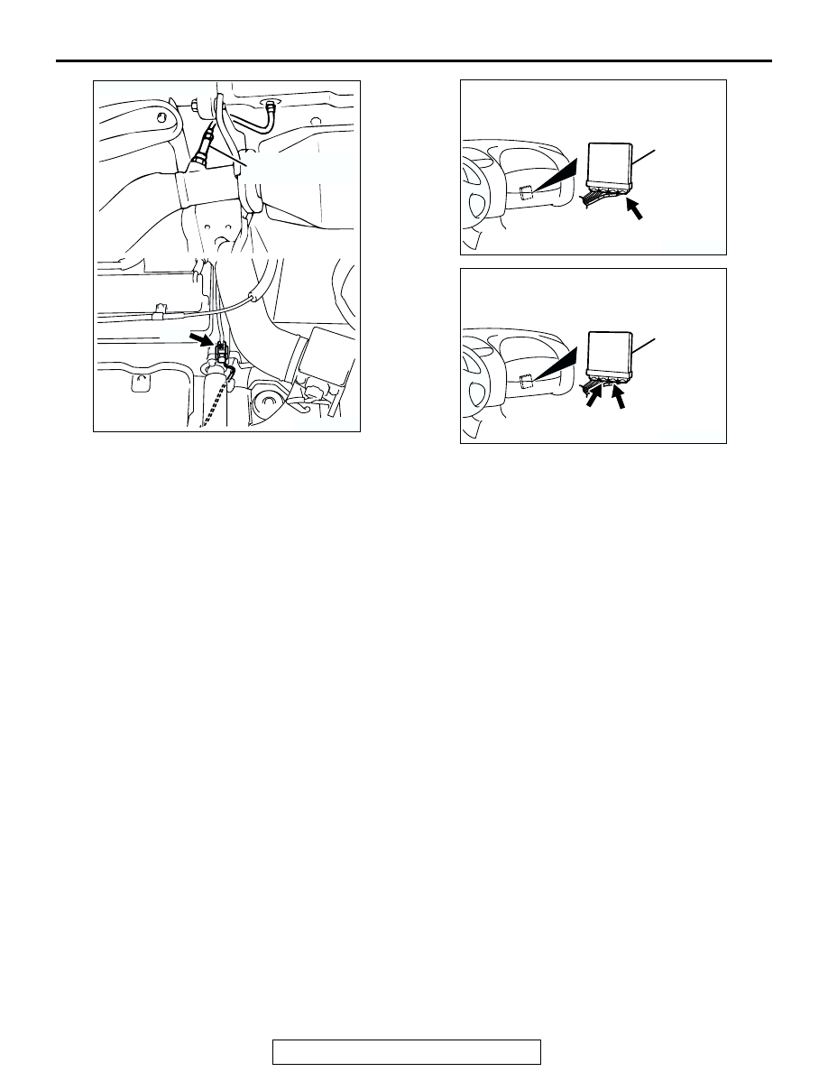
AK300054AB
C-23
HEATED OXYGEN
SENSOR (REAR)
CONNECTOR: C-23
AK300060
ECM
CONNECTOR: C-60 <M/T>
AE
C-60 (G)
AK300060
PCM
CONNECTORS: C-54, C-57 <A/T>
AI
C-57 (GR)
C-54 (GR)