Mitsubishi Eclipse. Manual - part 202
MULTIPORT FUEL INJECTION (MFI) DIAGNOSIS
TSB Revision
MULTIPORT FUEL INJECTION (MFI) <2.4L>
13A-301
STEP 5. Test the OBD-II drive cycle.
(1) Carry out a test drive with the drive cycle pattern. Refer to
Diagnostic Function
− OBD-II Drive Cycle − Procedure 6 −
Other Monitor
(2) Check the diagnostic trouble code (DTC).
Q: Is DTC P0137 set?
YES : Retry the troubleshooting.
NO : The inspection is complete.
AK300415
82
78
8180
89
90
91
92
79
87
71
74 73 72
76 75
77
85
88
83
84
86
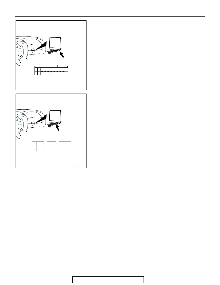
CONNECTOR: C-60 <M/T>
AB
C-60 (G)
HARNESS CONNECTOR:
COMPONENT SIDE
AK300735
98
78
71
88
89
76
77
72
79
91
73
80
74
75
81
92
82
83
93
84
85
94
86
87
95
96
90
97
CONNECTOR: C-57 <A/T>
C-57 (GR)
AB
HARNESS CONNECTOR:
COMPONENT SIDE