Mitsubishi Eclipse. Manual - part 153


  Index      Mitsubishi     Mitsubishi Eclipse - service repair manual 2004 year


Search            


Content   ..  151  152  153  154   ..


Mitsubishi Eclipse. Manual - part 153


MULTIPORT FUEL INJECTION (MFI) DIAGNOSIS

TSB Revision

MULTIPORT FUEL INJECTION (MFI) <2.4L>

13A-105

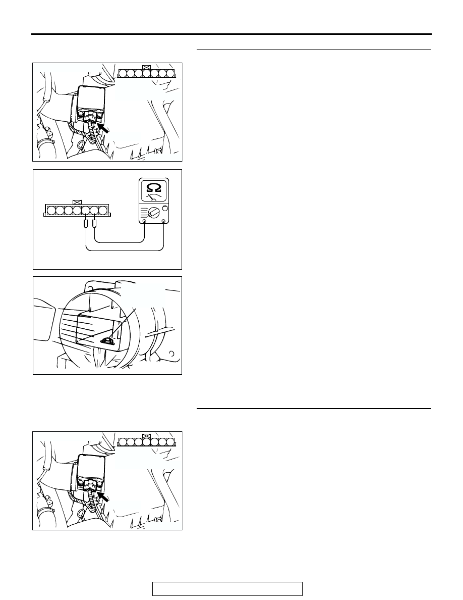
STEP 2. Check the intake air temperature sensor.
(1) Disconnect the intake air temperature sensor connector 

B-14.

(2) Measure the resistance between intake air temperature 

sensor side connector terminal No. 5 and No. 6.

(3) Measure resistance while heating the sensor using a hair 

drier.

Standard value:

13 

 17 k [at 20°C (4°F)]

5.3 

 6.7 k [at 0°C (32°F)]

2.3 

 3.0 k [at 20°C (68°F)]

1.0 

 1.5 k [at 40°C (104°F)]

0.56 

 0.76 k [at 60°C (140°F)]

0.30 

 0.42 k [at 80°C (176°F)]

Q: Is the resistance at the standard value?

YES : Go to Step 3.
NO :  Replace the volume airflow sensor. Then go to Step 9.

STEP 3. Check connector B-14 at the intake air 
temperature sensor for damage.
Q: Is the connector in good condition?

YES : Go to Step 4.
NO :  Repair or replace it. Refer to GROUP 00E, Harness 

Connector Inspection 

P.00E-2

. Then go to Step 9.

AK300078

3

4

5

1

2

6

7

CONNECTOR: B-14

AB

B-14 (B)

HARNESS 
CONNECTOR:
COMPONENT SIDE

AK000319AB

1 2 3 4 5 6 7

INTAKE AIR TEMPERATURE
SENSOR SIDE CONNECTOR

AKX01621 AB

INTAKE AIR
TEMPERATURE
SENSOR

AK300078

3

4

5

1

2

6

7

CONNECTOR: B-14

AB

B-14 (B)

HARNESS 
CONNECTOR:
COMPONENT SIDE

MULTIPORT FUEL INJECTION (MFI) DIAGNOSIS

TSB Revision

MULTIPORT FUEL INJECTION (MFI) <2.4L>

13A-106

STEP 4. Check the continuity at intake air temperature 
sensor harness side connector B-14.
(1) Disconnect the connector B-14 and measure at the harness 

side.

(2) Check for the continuity between terminal No. 5 and 

ground.

• Should be less than 2 ohms.

Q: Is the continuity normal?

YES : Go to Step 7.
NO :  Go to Step 5.

AK300078

3

4

5

1

2

6

7

CONNECTOR: B-14

AB

B-14 (B)

HARNESS 
CONNECTOR:
COMPONENT SIDE

AKX01409AI

7 6 5 4 3 2 1

B-14 HARNESS 
CONNECTOR: 
COMPONENT SIDE

MULTIPORT FUEL INJECTION (MFI) DIAGNOSIS

TSB Revision

MULTIPORT FUEL INJECTION (MFI) <2.4L>

13A-107

STEP 5. Check connector C-53 at ECM <M/T> or connector 
C-50 at PCM <A/T> for damage.
Q: Is the connector in good condition?

YES : Go to Step 6.
NO :  Repair or replace it. Refer to GROUP 00E, Harness 

Connector Inspection 

P.00E-2

. Then go to Step 9.

AK300417

34 33 32

36 35

37

42

45

31

39

38

46

40

41

43

44

CONNECTOR: C-53 <M/T>

C-53 (G)

AB

HARNESS CONNECTOR:
COMPONENT SIDE

AK300414

2

3

4

5

6

7

8

9

11

12

13

14

15

16

17

18

19

20

30

21

22

23

24

25

26

27

28

29

31

32

33

34

35

1

10

C-50 (GR)

CONNECTOR: C-50 <A/T>

AB

HARNESS CONNECTOR:
COMPONENT SIDE

MULTIPORT FUEL INJECTION (MFI) DIAGNOSIS

TSB Revision

MULTIPORT FUEL INJECTION (MFI) <2.4L>

13A-108

STEP 6. Check for open circuit and harness damage 
between intake air temperature sensor connector B-14 and 
ECM connector C-53 <M/T> or PCM connector C-50 <A/T>.
Q: Is the harness wire in good condition?

YES : Replace the ECM or PCM. Then go to Step 9.
NO :  Repair it. Then go to Step 9.

AK300078

3

4

5

1

2

6

7

CONNECTOR: B-14

AB

B-14 (B)

HARNESS 
CONNECTOR:
COMPONENT SIDE

AK300417

34 33 32

36 35

37

42

45

31

39

38

46

40

41

43

44

CONNECTOR: C-53 <M/T>

C-53 (G)

AB

HARNESS CONNECTOR:
COMPONENT SIDE

AK300414

2

3

4

5

6

7

8

9

11

12

13

14

15

16

17

18

19

20

30

21

22

23

24

25

26

27

28

29

31

32

33

34

35

1

10

C-50 (GR)

CONNECTOR: C-50 <A/T>

AB

HARNESS CONNECTOR:
COMPONENT SIDE


Content   ..  151  152  153  154   ..