Mitsubishi Eclipse. Manual - part 129


  Index      Mitsubishi     Mitsubishi Eclipse - service repair manual 2004 year


Search            


Content   ..  127  128  129  130   ..


Mitsubishi Eclipse. Manual - part 129


MULTIPORT FUEL INJECTION (MFI) DIAGNOSIS

TSB Revision

MULTIPORT FUEL INJECTION (MFI) <2.4L>

13A-9

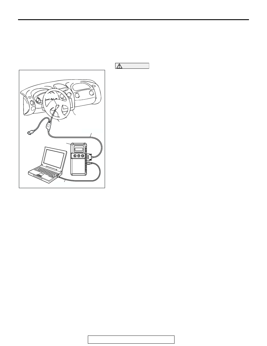
HOW TO CONNECT THE SCAN TOOL (MUT-III)

Required Special Tools:

• MB991958: Scan Tool (MUT-III Sub Assembly)

• MB991824: V.C.I

• MB991827: USB Cable

• MB991911: Main Harness B

CAUTION

To prevent damage to scan tool MB991958, always turn the 
ignition switch to the "LOCK" (OFF) position before con-
necting or disconnecting scan tool MB991958.
1. Ensure that the ignition switch is at the "LOCK" (OFF) 

position.

2. Start up the personal computer.
3. Connect special tool MB991827 to special tool MB991824 

and the personal computer.

4. Connect special tool MB991911 to special tool MB991824.
5. Connect special tool MB991911 to the data link connector.
6. Turn the power switch of special tool MB991824 to the "ON" 

position.
NOTE: When the special tool MB991824 is energized, spe-
cial tool MB991824 indicator light will be illuminated in a 
green color.

7. Start the MUT-III system on the personal computer.

NOTE: Disconnecting the scan tool MB991958 is the 
reverse of the connecting sequence, making sure that the 
ignition switch is at the "LOCK" (OFF) position.

HOW TO READ AND ERASE DIAGNOSTIC 
TROUBLE CODE

.

Required Special Tools:

• MB991958: Scan Tool (MUT-III Sub Assembly)

• MB991824: V.C.I

• MB991827: USB Cable

• MB991911: Main Harness B

AK300810

AB

MB991911

16-PIN

MB991827

MB991824 

MULTIPORT FUEL INJECTION (MFI) DIAGNOSIS

TSB Revision

MULTIPORT FUEL INJECTION (MFI) <2.4L>

13A-10

CAUTION

To prevent damage to scan tool MB991958, always turn the 
ignition switch to the "LOCK" (OFF) position before con-
necting or disconnecting scan tool MB991958.
NOTE: If the battery voltage is low, diagnostic trouble codes will 
not be set. Check the battery if scan tool MB991958 does not 
display.
1. Connect scan tool MB991958 to the data link connector.
2. Turn the ignition switch to the "ON" position.
3. Select "Interactive Diagnosis" from the start-up screen.
4. Select "System select."
5. Choose "MFI" from the "POWER TRAIN" tab.
6. Select "MITSUBISHI."
7. Select "Diagnostic Trouble Code"
8. If a DTC is set, it is shown.
9. Choose "Erase DTCs" to erase the DTC.

PROVISIONAL DTCs [SCAN TOOL MB991958 
OBD-II Test Mode 

 Results (Mode 7)]

The scan tool will display the Provisional DTCs reported by 
engine control module (ECM) <M/T> or powertrain control 
module (PCM) <A/T> if the ECM <M/T> or PCM <A/T> detects 
some malfunction for "Misfire", "Fuel System" and "Compre-
hensive" monitoring during a SINGLE Driving Cycle. The 
intended use of this data is to assist the technician after a vehi-
cle repair, and after clearing diagnostic information, by report-
ing test result after a SINGLE Driving Cycle. Note that the test 
results reported by this mode do not necessarily indicate a 
faulty component/system. If test results indicate a failure after 
ADDITIONAL (consecutive) driving, then the MIL will be illumi-
nated and a DTC will set.

MODE 6 REFERENCE TABLE

The engine control module (ECM) <M/T> or powertrain control module (PCM) <A/T> monitors the condition 
of emission control system. 
By selecting MODE 6 using scan tool, Test Result and Limit Value (minimum) *1 or (maximum) *2 about the 
main items of emission control system which ECM <M/T> or PCM <A/T> monitors can be confirmed. The 
value at the last monitoring is output by ECM <M/T> or PCM <A/T> as a test result.

AK300810

AB

MB991911

16-PIN

MB991827

MB991824 

MULTIPORT FUEL INJECTION (MFI) DIAGNOSIS

TSB Revision

MULTIPORT FUEL INJECTION (MFI) <2.4L>

13A-11

NOTE: 

.

*1: The test fails if test value is less than this value. 
*2: The test fails if test value is greater than this value. 

TEST 
ID

MONITORING 
ITEM

SIMPLE TECHNICAL DESCRIPTION INDICATION OF 

SCAN TOOL

CONVERSION 
COEFFICIENT IN 
USING GENERAL 
SCAN TOOL

01

Catalyst 
monitor

ECM <M/T> or PCM <A/T> monitors 
the deterioration of catalyst by the 
output frequency ratio between 
heated oxygen sensor (front) and 
heated oxygen sensor (rear).

Catalyst Frequency 
Ratio
Test Result and Limit 
Value (max.)

× 0.0039

03

EGR monitor

ECM <M/T> or PCM <A/T> monitors 
the operation of EGR system by the 
pressure difference of intake manifold 
between before and after introduction 
of EGR using the manifold absolute 
pressure sensor.

EGR Monitor 
Pressure Value
Test Result and Limit 
Value (min.)   kPa

× 0.43 kPa

06

Evaporation 
leak monitor 
(Small leak)

ECM <M/T> or PCM <A/T> monitors 
the leak of fuel evaporation gas by the 
reduction of vacuum in tank after 
appointed time using the fuel tank 
differential pressure sensor after 
making the fuel tank and the fuel line 
vacuum.

EVAP Leak Mon. 1 
mm Pressure Value
Test Result and Limit 
Value (max.)   kPa

× 0.032 kPa

07

Evaporation 
leak monitor 
(Gross leak)

ECM <M/T> or PCM <A/T> monitors 
the leak of fuel evaporation gas by the 
reduction of vacuum in tank after 
appointed time using the fuel tank 
differential pressure sensor after 
making the fuel tank and the fuel line 
vacuum.

EVAP Leak Mon. 
Gross Pressure Value
Test Result and Limit 
Value (min.)   kPa

× 0.032 kPa

08

Evaporation 
leak monitor 
(Very small 
leak)

ECM <M/T> or PCM <A/T> monitors 
the leak of fuel evaporation gas by the 
reduction of vacuum in tank after 
appointed time using the fuel tank 
differential pressure sensor after 
making the fuel tank and the fuel line 
vacuum.

EVAP Leak Mon. 0.5 
mm Pressure Value
Test Result and Limit 
Value (max.)   kPa

× 0.032 kPa

09

Heated oxygen 
sensor (front) 
monitor 
(Rich/Lean 
switching) 

ECM <M/T> or PCM <A/T> monitors 
the deteriorated condition of the 
heated oxygen sensor (front) by 
checking the lean/rich switching 
frequency of the heated oxygen 
sensor (front). 

HO2S B1 SENSOR1 
Rich/Lean switching 
Count
Test Result and Limit 
Value (min.)

× 1count

0B

Heated oxygen 
sensor (rear) 
monitor 
(Voltage) 

ECM<M/T> or PCM<A/T> checks the 
output voltage of the heated oxygen 
sensor (rear) in order to monitor 
whether the heated oxygen sensor 
(rear) output is stuck.

HO2S B1 SENSOR2 
Change in Volt
Test Result and Limit 
Value (min.)

× 19.5 mV

MULTIPORT FUEL INJECTION (MFI) DIAGNOSIS

TSB Revision

MULTIPORT FUEL INJECTION (MFI) <2.4L>

13A-12

DIAGNOSTIC BY DIAGNOSTIC TEST MODE II 
(INCREASED SENSITIVITY)

Required Special Tools:

• MB991958 (MUT-III Sub Assembly)

• MB991824: V.C.I.

• MB991827: USB Cable

• MB991911: Main Harness B

CAUTION

To prevent damage to scan tool MB991958, always turn the 
ignition switch to the "LOCK" (OFF) position before con-
necting or disconnecting scan tool MB991958.
NOTE: When mode II is selected with scan tool MB991958 
(MUT-III sub assembly), the Malfunction Indicator Lamp (SER-
VICE ENGINE SOON or Check Engine Lamp) will light when 
the engine control module (ECM) <M/T> or powertrain control 
module (PCM) <A/T> first detects the trouble (Note that this is 
only for emission-related trouble). At the same time, the rele-
vant diagnostic trouble codes will be registered. In respect to 
the comprehensive component electrical faults (opens/shorts), 
the time for the diagnostic trouble code to be registered after 
the fault occurrence is four seconds 

 one second. Therefore, 

the confirmation of the trouble symptom and the confirmation 
after completing repairs can be reduced. To return to the nor-
mal mode I after mode II has been selected once, the ignition 
switch must be turned "OFF" once or mode I must be rese-
lected with scan tool MB991958 (MUT-III sub assembly). The 
diagnostic trouble code, system readiness test status and 
freeze frame data, etc., will be erased when mode I is returned 
to, so record these before returning to mode I.
1. Connect scan tool MB991958 to the data link connector.
2. Turn the ignition switch to the "ON" position.
3. Change the diagnostic test mode of the ECM <M/T> or PCM 

<A/T> to DIAGNOSTIC TEST MODE II (INCREASED 
SENSITIVITY).

4. Road test the vehicle.
5. Read the diagnostic trouble code and repair the 

malfunctioning part.

6. Turn the ignition switch to the "LOCK" (OFF) position.
7. Disconnect scan tool MB991958 from the data link 

connector.

AK300810

AB

MB991911

16-PIN

MB991827

MB991824 


Content   ..  127  128  129  130   ..