Mitsubishi Eclipse. Manual - part 128
MULTIPORT FUEL INJECTION (MFI) DIAGNOSIS
TSB Revision
MULTIPORT FUEL INJECTION (MFI) <2.4L>
13A-5
MULTIPORT FUEL INJECTION (MFI) DIAGNOSIS
TROUBLESHOOTING STRATEGY
M1131150000513
Use these steps to plan your diagnostic strategy. If
you follow them carefully, you will be sure to have
exhausted most of the possible ways to find an MFI
fault.
1. Gather as much information as possible about the
complaint from the customer.
2. Verify that the condition described by the
customer exists.
3. Check the vehicle for any MFI Diagnostic Trouble
Code (DTC).
4. If you cannot verify the condition and there are no
DTCs, the malfunction is intermittent. For
information on how to cope with intermittent
malfunctions, refer to GROUP 00, How to Use
Troubleshooting/Inspection Service Points
− How
to cope with Intermittent Malfunction
5. If you can verify the condition but there are no
DTCs, or the system cannot communicate with
the scan tool, refer to the trouble symptom
classification table.
6. If there is a DTC, record the number of the code,
then erase the code from the memory using the
scan tool.
NOTE: If a DTC is erased, its "freeze frame" data will
be also erased and the system readiness test status
will be reset. If necessary, store the "freeze frame"
data before erasing the DTC.
7. Reconfirm the malfunction symptom and carry out
a test drive with the drive cycle pattern.
8. If DTC is set again, carry out an inspection with
the inspection procedure for diagnostic trouble
codes of that code.
9. If DTC is not set again, the malfunction is
intermittent. For information on how to cope with
intermittent malfunctions, refer to GROUP 00,
How to Use Troubleshooting/Inspection Service
Points
− How to cope with Intermittent Malfunction
10.After repairs are completed, conduct a road test
duplicating the complaint set conditions to confirm
the malfunction has been eliminated.
NOTE: If the engine control module (ECM) <M/T> or
powertrain control module (PCM) <A/T> is replaced,
Immobilizer Encrypted Code Registration should be
carried out. Refer to GROUP 54A, Ignition Switch
−
On-vehicle Service
−
Immobilizer Encrypted Code
Registration
DIAGNOSTIC FUNCTION
M1131155500159
.
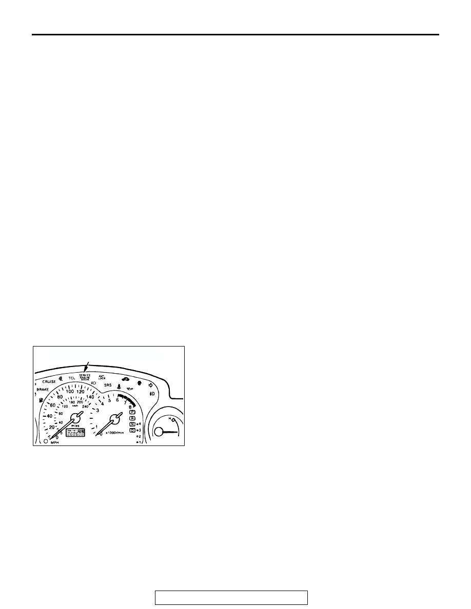
MALFUNCTION INDICATOR LAMP (SERVICE ENGINE
SOON OR CHECK ENGINE LAMP)
Among the on-board diagnostic items, a Malfunction Indicator
Lamp (SERVICE ENGINE SOON or Check Engine Lamp) illu-
minates to notify the driver of an emission control malfunction.
However, when an irregular signal returns to normal and the
engine control module (ECM) <M/T> or powertrain control
module (PCM) <A/T> judges that it has returned to normal, the
Malfunction Indicator Lamp (SERVICE ENGINE SOON or
Check Engine Lamp) is switched off.
Moreover, when the ignition switch is turned off, the lamp is
switched off. Even if the ignition switch is turned on again, the
lamp does not illuminate until the malfunction is detected.
Immediately after the ignition switch is turned on, the Malfunc-
tion Indicator Lamp (SERVICE ENGINE SOON or Check
Engine Lamp) is lit for 20 seconds to indicate that the Malfunc-
tion Indicator Lamp (SERVICE ENGINE SOON or Check
Engine Lamp) operates normally.
.
AK000054
AB
MALFUNCTION INDICATOR LAMP
(SERVICE ENGINE SOON OR
CHECK ENGINE LAMP)
AD