Mitsubishi Eclipse. Manual - part 119


  Index      Mitsubishi     Mitsubishi Eclipse - service repair manual 2004 year


Search            


Content   ..  117  118  119  120   ..


Mitsubishi Eclipse. Manual - part 119


ENGINE ASSEMBLY

TSB Revision

ENGINE MECHANICAL <3.0L>

11C-25

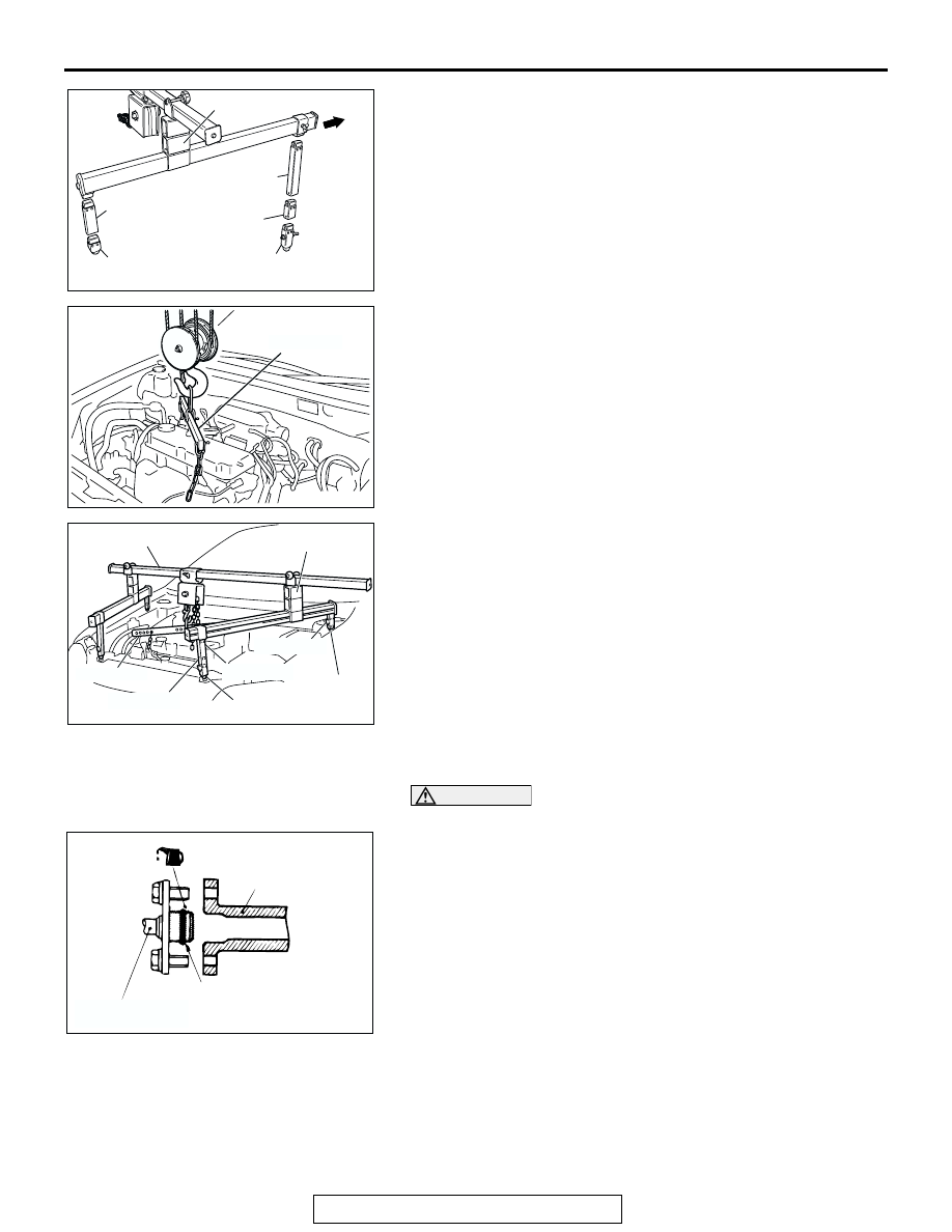
(1) Assemble the engine hanger (special tool 

MB991928).Set following parts the base hanger. 

• Slide bracket (HI)

• Foot (standard) (MB991932)

• Foot (short) (MB991933)

• Joint (50) (MB991929)

• Joint (90) (MB991930)

• Joint (140) (MB991931)

(2) Remove the chain block and support the engine 

assembly with special tools MB991895.

.

>>D<< FUEL HIGH-PRESSURE HOSE INSTALLATION

CAUTION

Do not allow engine oil to enter the fuel rail.
1. Apply a small amount of new engine oil to the O-ring.
2. Turning the fuel high-pressure hose to the right and left, 

install it to the fuel rail, while being careful not to damage the 
O-ring. After installing, check that the hose turns smoothly.

3. If the hose does not turn smoothly, the O-ring may be 

clamped. Disconnect the fuel high-pressure hose and check 
the O-ring for damage. 

4. Re-insert the fuel rail and check that the hose turns 

smoothly.

AC302468

FOOT (SHORT) (MB991933)

JOINT (90)
(MB991930)

FOOT (STANDARD)
(MB991932)

JOINT (50)
(MB991929)

JOINT (140)
(MB991931)

FRONT S

SLIDE BRACKET (HI)

AB

AC102341AC

MB991454

AC302400AC

MB991928

SLIDE BRACKET (HI)

MB991454

MB991932

MB991931

MB991933

MB991929

MB991930

AC000129 AB

FUEL RAIL

HIGH-PRESSURE
FUEL HOSE

O-RING

CAMSHAFT AND CAMSHAFT OIL SEAL

TSB Revision

ENGINE MECHANICAL <3.0L>

11C-26

CAMSHAFT AND CAMSHAFT OIL SEAL

REMOVAL AND INSTALLATION

M1112001900325

<LEFT BANK>

Required Special Tools:

• MB990767: End Yoke Holder
• MB991559: Camshaft Oil Seal Adapter
• MD998443: Auto-lash Adjuster Holder
• MD998713: Camshaft Oil Seal Installer
• MD998715: Crankshaft Pulley Holder Pin

Pre-removal and Post-installation Operation
Timing Belt Removal and Installation (Refer to 

P.11C-41

.)

AC004834

APPLY ENGINE OIL TO
ALL THE MOVING PARTS
WHEN INSTALLING

(ENGINE OIL)

3.4 ± 0.5 N·m
31 ± 4 in-lb

13 ± 2 N·m
109 ± 21 in-lb

88 ± 10 N·m
65 ± 7 ft-lb

31 ± 3 N·m
23 ± 2 ft-lb

1

2

3

5

6

7

8

10

11

AC

4

N

9

N

CAMSHAFT REMOVAL STEPS

THERMOSTAT HOUSING 
ASSEMBLY (REFER TO GROUP 
14, WATER HOSE AND PIPE 

P.14-28

.)

1.

BLOW-BY HOSE CONNECTION

2.

PCV HOSE CONNECTION

3.

SPARK PLUG CABLE

4.

BATTERY CABLE CONNECTION

5.

ROCKER COVER

<<A>> >>D<<

6.

ROCKER ARM AND SHAFT 
ASSEMBLY

<<B>> >>B<<

7.

CAMSHAFT SPROCKET

9.

BATTERY CABLE AND 
HARNESS BRACKET

10. THRUST CASE
11. CAMSHAFT

CAMSHAFT OIL SEAL 
REMOVAL STEPS

<<B>> >>B<<

7.

CAMSHAFT SPROCKET

>>A<<

8.

CAMSHAFT OIL SEAL

CAMSHAFT REMOVAL STEPS 

CAMSHAFT AND CAMSHAFT OIL SEAL

TSB Revision

ENGINE MECHANICAL <3.0L>

11C-27

<RIGHT BANK>

Required Special Tools:

• MB990767: End Yoke Holder
• MD998443: Auto-lash Adjuster Holder
• MD998713: Camshaft Oil Seal Installer
• MD998715: Crankshaft Pulley Holder Pin

Pre-removal and Post-installation Operation
Timing Belt Removal and Installation (Refer to 

P.11C-41

.)

AC001717AB

3.4 ± 0.5 N·m
31 ± 4 in-lb

13 ± 2 N·m
109 ± 21 in-lb

31 ± 3 N·m
23 ± 2 ft-lb

88 ± 10 N·m
65 ± 7 ft-lb

APPLY ENGINE OIL TO
ALL THE MOVING PARTS
WHEN INSTALLING

1

2

3

4

5

6

7

8

9

CAMSHAFT REMOVAL STEPS

INTAKE MANIFOLD PLENUM 
(REFER TO GROUP 15, INTAKE 
MANIFOLD PLENUM 

P.15-7

.)

1.

BREATHER HOSE 
CONNECTION

2.

BLOW-BY HOSE CONNECTION

3.

SPARK PLUG CABLE

4.

ROCKER COVER

<<A>> >>D<<

5.

ROCKER ARM AND SHAFT 
ASSEMBLY

>>C<<

6.

DISTRIBUTOR

<<B>> >>B<<

7.

CAMSHAFT SPROCKET

9.

CAMSHAFT
CAMSHAFT OIL SEAL 
REMOVAL STEPS

<<B>> >>B<<

7.

CAMSHAFT SPROCKET

>>A<<

8.

CAMSHAFT OIL SEAL

CAMSHAFT REMOVAL STEPS 

CAMSHAFT AND CAMSHAFT OIL SEAL

TSB Revision

ENGINE MECHANICAL <3.0L>

11C-28

REMOVAL SERVICE POINTS

.

<<A>> ROCKER ARM AND SHAFT ASSEMBLY REMOVAL
1. Install special tool MD998443 as shown in the illustration so 

that the lash adjusters will not fall out.

CAUTION

Never disassemble the rocker arm and shaft assembly.
2. Loosen the rocker arm and shaft assembly mounting bolts, 

then remove the rocker arm and shaft assembly with the 
bolts still attached.

.

<<B>> CAMSHAFT SPROCKET REMOVAL
1. Use special tools MB990767 and MD998715 to loosen the 

camshaft sprocket mounting bolt.

2. Remove the camshaft sprocket.

INSTALLATION SERVICE POINTS

.

>>A<< CAMSHAFT OIL SEAL INSTALLATION
1. Apply engine oil to the camshaft oil seal lip.
2. Use special tools MB991559 and MD998713 to press-fit the 

camshaft oil seal.

.

>>B<< CAMSHAFT SPROCKET INSTALLATION
1. Install the camshaft sprocket.

AC001718

MD998443

AB

ACX00301AB

MB990767

MD998715

AC001719 AB

MD998713

MB991559 MD998713

LEFT BANK

RIGHT BANK


Content   ..  117  118  119  120   ..