Mitsubishi Eclipse. Manual - part 115
ON-VEHICLE SERVICE
TSB Revision
ENGINE MECHANICAL <3.0L>
11C-9
CAUTION
To prevent damage to scan tool MB991958, always turn the
ignition switch to the "LOCK" (OFF) position before con-
necting or disconnecting scan tool MB991958.
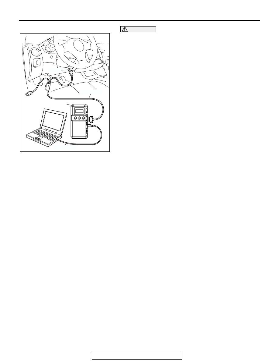
2. Connect scan tool MB991958 to the data link connector.
3. Check that the basic ignition timing is within the standard
value.
Standard value: 5
° BTDC ± 3°
4. Start the engine and increase the engine speed to 2,500
r/min for 2 minutes.
5. Set the CO, HC tester.
6. Check the CO contents and the HC contents at idle.
Standard value:
CO contents: 0.5 % or less
HC contents: 100 ppm or less
7. If the CO and HC contents do not remain inside the standard
value, check the following items:
NOTE: Replace the catalytic converter when the CO and HC
contents do not remain inside the standard value, even
though the result of the inspection is normal for all items.
• Diagnostic output
• Closed-loop control (When the closed-loop control is carried
out normally, the output signal of the heated oxygen sensor
changes between 0
− 400 mV and 600 − 1,000 mV at idle.)
• Fuel pressures
• Injector
• Ignition coil, spark plug cable, spark plug
• EGR system and EGR valve leak
• Evaporative emission system
• Compression pressure
CURB IDLE SPEED CHECK
M1111003500524
Required Special Tool:
MB991958: Scan Tool (MUT-III Sub Assembly)
• MB991824: V.I.C.
• MB991827: USB Cable
• MB991911: Main Harness B
1. Before inspection and adjustment set vehicles in the
following condition.
• Engine coolant temperature: 80 − 95°C (176 − 203°F)
• Lights and all accessories: OFF
• Transaxle: Neutral (P range on vehicles with A/T)
AK301853
AB
MB991911
16-PIN
MB991827
MB991824