Mitsubishi Eclipse. Manual - part 89
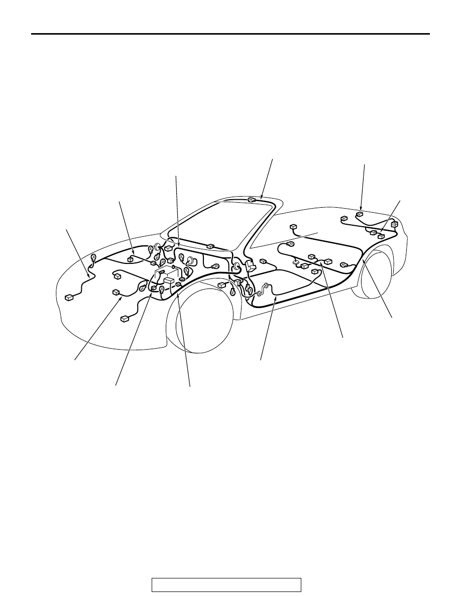
OVERALL CONFIGURATION DIAGRAM <ECLIPSE SPYDER>
TSB Revision
CONFIGURATION DIAGRAMS
80A-3
OVERALL CONFIGURATION DIAGRAM
<ECLIPSE SPYDER>
M1801000100332
NOTE:
.
1. This illustration shows only major wiring harnesses.
2. *: also equipped at the right side.
AC101824
FRONT WIRING
HARNESS (RH)
AB
INJECTOR WIRING
HARNESS
INSTRUMENT PANEL
WIRING HARNESS
ROOF WIRING
HARNESS
TRUNK LID
WIRING HARNESS
REAR
BUMPER
WIRING
HARNESS
FLOOR WIRING
HARNESS
FUEL WIRING
HARNESS
DOOR WIRING
HARNESS*
FRONT WIRING
HARNESS (LH)
CONTROL WIRING
HARNESS
BATTERY WIRING
HARNESS