Mitsubishi Eclipse. Manual - part 5
CENTRALIZED JUNCTION
TSB Revision
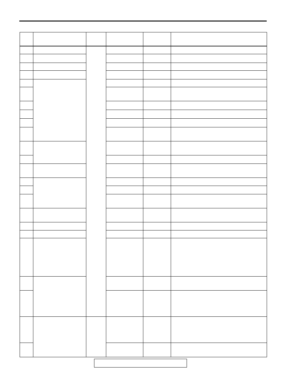
CIRCUIT DIAGRAMS
90-17
PASSENGER COMPARTMENT
NO. POWER SUPPLY
CIRCUIT
NAME RATED
CAPACITY (A)
HOUSING
COLOR
LOAD CIRCUIT
1
Fusible link No.5
Fuse
20
Yellow
Amplifier
2
−
−
−
−
3
Fusible link No.5
20
Yellow
Sunroof motor assembly
4
−
−
−
−
5
Fusible link No.1
30
Green
Capacitor, choke coil and defogger
6
30
Green
Automatic compressor controller, blower
motor and resistor
7
−
−
−
8
−
−
−
9
−
−
−
10
15
Blue
Combination meter, data link connector
and ETACS-ECU
11
Ignition switch (ACC)
15
Blue
Capacitor, ETACS-ECU, rear washer
motor and rear wiper motor
12
−
−
−
13
Ignition switch (IG2)
7.5
Brown
ABS-ECU, convertible top control
module and sunroof motor assembly
14
Ignition switch (ACC)
7.5
Brown
Remote controlled mirror
15
−
−
−
16
15
Blue
Accessory socket, cigarette lighter and
multi center display unit
17
Ignition switch (IG1)
7.5
Brown
Engine control module, fuel pump relay
and powertrain control module
18
Ignition switch (ACC)
20
Yellow
Front-ECU and windshield wiper motor
19
Defogger relay
7.5
Brown
Remote controlled mirror
20
Ignition switch (IG2)
7.5
Brown
A/C compressor relay, A/C switch,
automatic compressor controller, blower
relay, defogger relay, front-ECU,
outside/inside air selection damper
control motor, water shut motor and
water shut valve controller
21
Ignition switch (IG1)
7.5
Brown
Auto-cruise control-ECU and auto-cruise
control switch
22
7.5
Brown
Backup light, combination meter,
ETACS-ECU, input shaft speed sensor,
output shaft speed sensor, powertrain
control module and SRS-ECU
23
Ignition switch (IG1)
Fuse
7.5
Brown
Column switch, combination meter,
ETACS-ECU, motor antenna assembly,
multi center display unit, SRS-ECU and
vehicle speed sensor
24
10
Red
Capacitor, distributor assembly and
ignition coil