Mitsubishi Colt Ralliart. Manual - part 737


  Index      Mitsubishi     Mitsubishi Colt Ralliart - service repair manual


Search            


Content   ..  735  736  737  738   ..


Mitsubishi Colt Ralliart. Manual - part 737


TROUBLESHOOTING

MULTIPORT FUEL INJECTION (MPI) <4G1>

13B-273

Inspection Procedure 19: Abnormal Rotation of Fan Motor
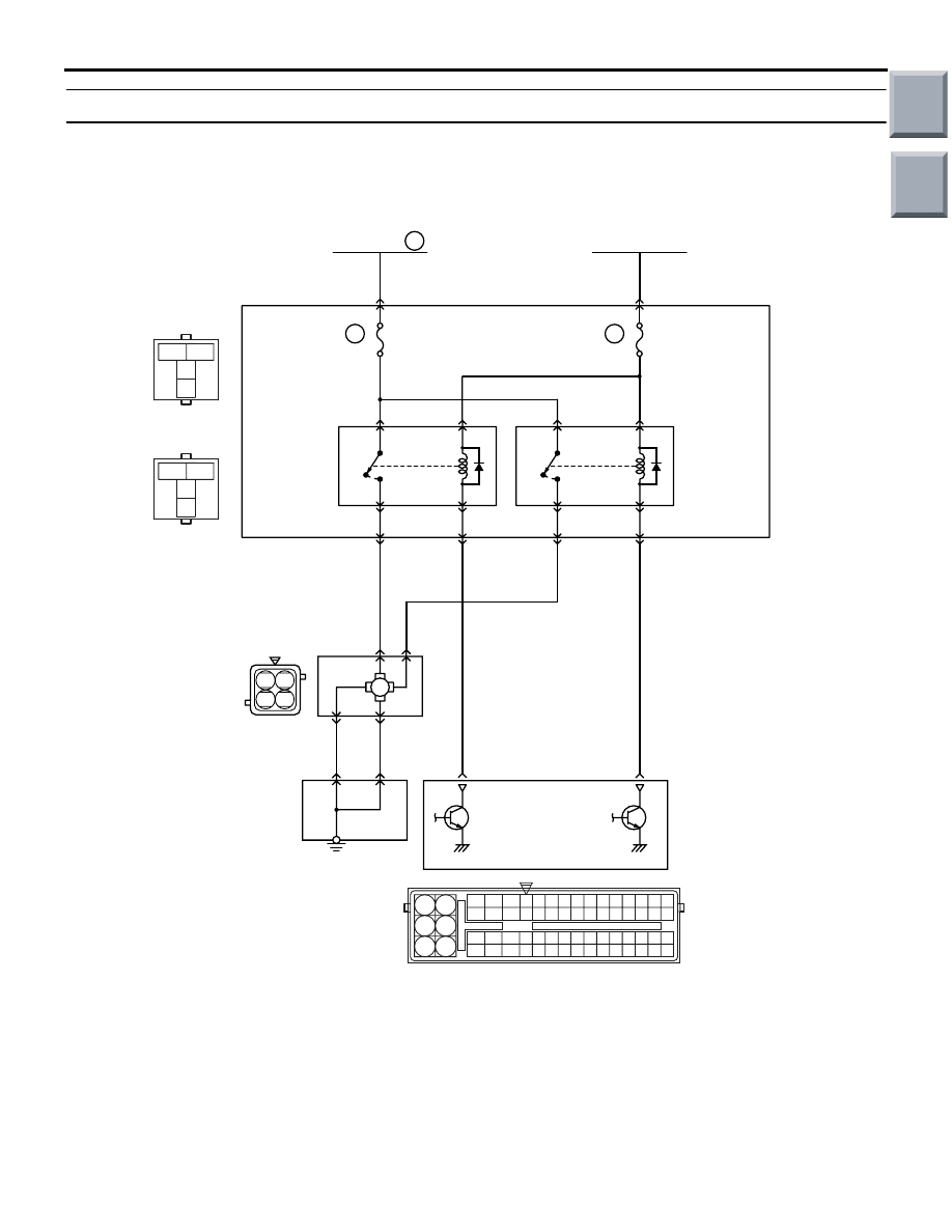
OPERATION

• The battery voltage is applied to the cooling fan 

control relay (LO) coil (terminal No. 1) and cool-
ing fan control relay (HI) coil (terminal No. 1) from 
the ignition switch.

• The engine-ECU (terminal No. 95 and No. 96) 

turns on the switch of the power transistor on the 
unit, and then turns on the switch of the relay by 
applying the electrical current to the cooling fan 
control relay (LO) coil or cooling fan control relay 
(HI) coil.

AK402838

M

3

1

2

4

3

1

2

4

1 2

3 4

R

92 93 94 95969798

77 78 79 808182838485868788899091

99

100

107 108 109 110 111112113114115116117118119120121
122 123 124 125126127128129130131132133134135136

101102103104105106

71 72

73 74

75 76

B-114

B-127

B-114

B-127

B-114

B-127

6

14

Cooling fan 
control
relay (LO)

Cooling 
fan 
motor 

J/C

B-114

Cooling fan 
control
relay (HI)

Engine-ECU

B-127

B-109

B-110

L-R

R-W

R-L

B-112

B-108

3

1

4

2

1

1

R

Fusible link

3

40A

L

B

B

J/B

2

17

95

96

B-109

B-130

1

3

4

2

3

L-R

Ignition switch (IG2)

41

7.5A

1

3

4

2

5

2

A-08

A-20

A-31

AC

Wire colour code
B: Black  LG: Light green  G: Green  L: Blue  W: White  Y: Yellow  SB: Sky blue  BR: Brown  O: Orange  GR: Gray
R: Red  P: Pink  V: Violet

  P: Purple

Cooling Fan Control Relay Circuit

Main

Index

Group

TOC

TROUBLESHOOTING

MULTIPORT FUEL INJECTION (MPI) <4G1>

13B-274

• When the cooling fan control relay (LO) is in ON 

position, the battery voltage is applied to the cool-
ing fan motor (terminal No. 1) from the cooling 
fan control relay (LO) (terminal No. 4).

• When the cooling fan control relay (LO) and cool-

ing fan control relay (HI) are in ON position, the 
battery voltage is applied to the cooling fan motor 
(terminal No. 3) from the cooling fan control relay 
(HI) (terminal No. 4).

FUNCTION

• When the cooling fan control relay (LO) is in ON 

position, the fan motor rotates with the low speed.

• When the cooling fan control relay (LO) and the 

cooling fan control relay (HI) are in ON position, 
the fan motor rotates with the high speed.

PROBABLE CAUSES

• Failed cooling fan motor

• Open/short circuit in or damage to the cooling fan 

control relay circuit or loose connector contact

• Failed engine-ECU

DIAGNOSIS PROCEDURE

STEP 1. Check cooling fan motor.

• Check cooling fan motor (Refer to GROUP 14 − 

On-vehicle Service 

− Cooling Fan Motor Inspec-

tion 

P.14-9

).

Q: Is the check result normal?

YES : 

Go to Step 2 .

NO : 

Replace cooling fan motor.

STEP 2. Connector check: A-08 engine-ECU 
connector

Q: Is the check result normal?

YES : 

Go to Step 3 .

NO : 

Repair or replace.

AK402725

77

78

79

80

81

82

83

84

92

93

94

95

96

97

98

99

85

86

87

88

89

90

91

100

101

102

103

104

105

106

115

116

117

118

119

120

121

107

108

109

110

111

112

113

114

130

131

132

133

134

135

136

122

123

124

125

126

127

128

129

72 71

74 73

76 75

R

AI

A-08

Connector: 

A-08

A-08 Special tool power plant ECU check 
harness

Engine-ECU

Battery

Main

Index

Group

TOC

TROUBLESHOOTING

MULTIPORT FUEL INJECTION (MPI) <4G1>

13B-275

STEP 3. Perform voltage measurement at A-08 
engine-ECU connector.

Disconnect connector and measure at harness side.

• Ignition switch: ON

• Voltage between terminal No. 95 and earth.

OK: System voltage

Q: Is the check result normal?

YES : 

Go to Step 5 .

NO : 

Go to Step 4 .

STEP 4. Connector check: B-114 cooling fan 
control relay (LO) connector

AK402725

77

78

79

80

81

82

83

84

92

93

94

95

96

97

98

99

85

86

87

88

89

90

91

100

101

102

103

104

105

106

115

116

117

118

119

120

121

107

108

109

110

111

112

113

114

130

131

132

133

134

135

136

122

123

124

125

126

127

128

129

72 71

74 73

76 75

R

AI

A-08

Connector: 

A-08

A-08 Special tool power plant ECU check 
harness

Engine-ECU

Battery

AK402106

3

2

1

4

AC

Connector: B-114

J/B side 
connector

B-114

AK402725

77

78

79

80

81

82

83

84

92

93

94

95

96

97

98

99

85

86

87

88

89

90

91

100

101

102

103

104

105

106

115

116

117

118

119

120

121

107

108

109

110

111

112

113

114

130

131

132

133

134

135

136

122

123

124

125

126

127

128

129

72 71

74 73

76 75

R

AI

A-08

Connector: 

A-08

A-08 Special tool power plant ECU check 
harness

Engine-ECU

Battery

Main

Index

Group

TOC

TROUBLESHOOTING

MULTIPORT FUEL INJECTION (MPI) <4G1>

13B-276

Q: Is the check result normal?

YES : 

Check intermediate connector B-110, and 

repair if necessary. If the intermediate 
connector is normal, check and repair 
harness between B-114 (terminal No. 2) 
cooling fan control relay (LO) connector and 
A-08 (terminal No. 95) engine-ECU 
connector.

• Check signal line for short circuit.

NO : 

Repair or replace.

STEP 5. Perform voltage measurement at A-08 
engine-ECU connector.

Disconnect connector and measure at harness side.

• Ignition switch: ON

• Voltage between terminal No. 96 and earth.

OK: System voltage

Q: Is the check result normal?

YES : 

Go to Step 7 .

NO : 

Go to Step 6 .

STEP 6. Connector check: B-127 cooling fan 
control relay (HI) connector

AK402725

77

78

79

80

81

82

83

84

92

93

94

95

96

97

98

99

85

86

87

88

89

90

91

100

101

102

103

104

105

106

115

116

117

118

119

120

121

107

108

109

110

111

112

113

114

130

131

132

133

134

135

136

122

123

124

125

126

127

128

129

72 71

74 73

76 75

R

AI

A-08

Connector: 

A-08

A-08 Special tool power plant ECU check 
harness

Engine-ECU

Battery

3

2

1

4

AK402107

J/B side 
connector

Connector: B-127
J/B (front side)

AC

B-127

AK402725

77

78

79

80

81

82

83

84

92

93

94

95

96

97

98

99

85

86

87

88

89

90

91

100

101

102

103

104

105

106

115

116

117

118

119

120

121

107

108

109

110

111

112

113

114

130

131

132

133

134

135

136

122

123

124

125

126

127

128

129

72 71

74 73

76 75

R

AI

A-08

Connector: 

A-08

A-08 Special tool power plant ECU check 
harness

Engine-ECU

Battery

Main

Index

Group

TOC


Content   ..  735  736  737  738   ..