Mitsubishi Colt Ralliart. Manual - part 730
TROUBLESHOOTING
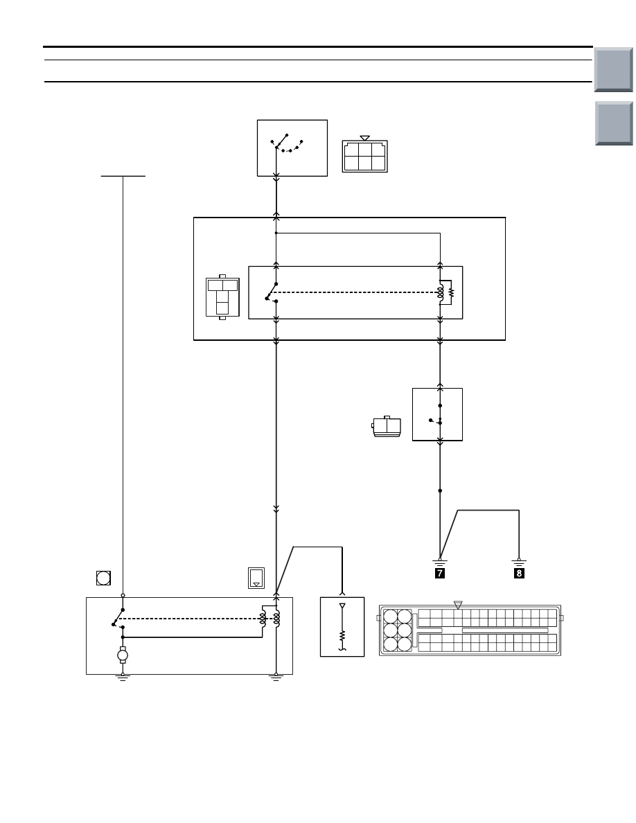
MULTIPORT FUEL INJECTION (MPI) <4G1>
13B-245
Inspection Procedure 4: Starting Impossible (No Initial Combustion)
OFF
ON
M
AK600524
1
1
19
21
20
18
17
16
15
14
1213
11
8 9
L
10
37
52 53 54 555657585960616263646566
38 39 404142434445464748495051
22 23 24 252627282930313233343536
7
5
3
1
6
4
2
2 1
1 2 3
4 5 6
3
1
2
4
R
IG2
ST
LOCK
ACC
IG1
Ignition switch
B-141
5
B-Y
B-129
6
1
2
J/B
B-Y
B-Y
Starter
relay
Clutch
switch
B-109
R-W
B-R
B-R
B-R
B-112
2
29
1
A-17
9
39
1
B-105
3
4
B
B
A-114
Engine-ECU
AB
Starter
1
1
A-124
A-125
OFF
ON
B-60
MU801670
OFF
ON
Battery
Wire colour code
B: Black LG: Light green G: Green L: Blue W: White Y: Yellow SB: Sky blue BR: Brown O: Orange GR: Gray
R: Red P: Pink V: Violet Pu: Purple
Main
Index
Group
TOC