Mitsubishi Colt Ralliart. Manual - part 723


  Index      Mitsubishi     Mitsubishi Colt Ralliart - service repair manual


Search            


Content   ..  721  722  723  724   ..


Mitsubishi Colt Ralliart. Manual - part 723


TROUBLESHOOTING

MULTIPORT FUEL INJECTION (MPI) <4G1>

13B-217

Code No. P2123: Accelerator Pedal Position Sensor (Main) Circuit High Input
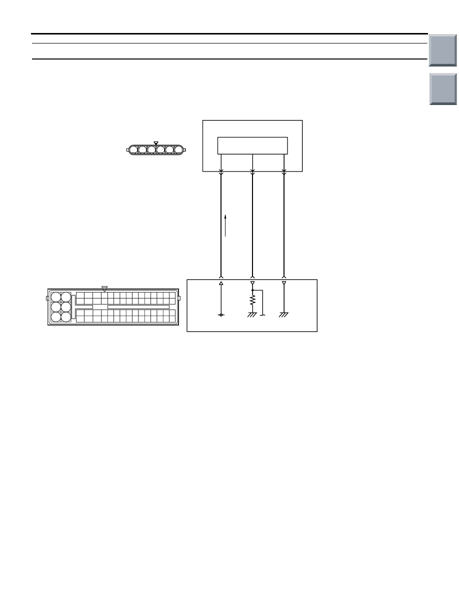
OPERATION

• A power voltage of 5 V is applied to the accelera-

tor pedal position sensor (terminal No. 1) from the 
engine-ECU (terminal No. 85).

• The power voltage is earthed to the engine-ECU 

(terminal No. 84) from the accelerator pedal posi-
tion sensor (terminal No. 2).

• The sensor signal is inputted to the engine-ECU 

(terminal No. 83) from the accelerator pedal posi-
tion sensor output terminal (terminal No. 3).

FUNCTION

• The accelerator pedal position sensor (main) out-

puts voltage which corresponds to the accelera-
tor pedal depression.

• The engine-ECU checks whether the voltage is 

within a specified range.

TROUBLE JUDGMENT

Check Conditions

• Ignition switch is in ON position.

Judgment Criterion

• Accelerator pedal position sensor (main) output 

voltage is more than 4.8 V.

PROBABLE CAUSE

• Failed accelerator pedal position sensor

• Open/short circuit in accelerator pedal position 

sensor circuit or loose connector contact

• Failed engine-ECU

AK402685

R

92 93 94 95969798

77 78 79 808182838485868788899091

99

100

107 108 109 110 111112113114115116117118119120121
122 123 124 125126127128129130131132133134135136

101102103104105106

71 72

73 74

75 76

6

1 2 3 4 5

5 V

85

1

Accelerator
pedal
position
sensor

(main)

Hall IC

Y-G

GR

BR-W

83

84

3

2

Accelerator Pedal Position Sensor (main) Circuit

A-08

B-26

Wire colour code
B: Black  LG: Light green  G: Green  L: Blue  W: White  Y: Yellow  SB: Sky blue  BR: Brown  O: Orange  GR: Gray
R: Red  P: Pink  V: Violet  P: Purple

AD

Engine-ECU

Main

Index

Group

TOC

TROUBLESHOOTING

MULTIPORT FUEL INJECTION (MPI) <4G1>

13B-218

DIAGNOSIS PROCEDURE

STEP 1. M.U.T.-III data list

• Refer to Data List Reference Table 

P.13B-335

.

a. Item 78: Accelerator pedal position sensor 

(main)

Q: Is the check result normal?

YES : 

Intermittent malfunction (Refer to GROUP 

00 

− How to Use 

Troubleshooting/Inspection Service Points 

− 

How to Cope with Intermittent Malfunctions 

P.00-13

).

NO : 

Go to Step 2 .

STEP 2. Connector check: B-26 accelerator pedal 
position sensor connector

Q: Is the check result normal?

YES : 

Go to Step 3 .

NO : 

Repair or replace.

STEP 3. Perform resistance measurement at B-26 
accelerator pedal position sensor connector.

• Disconnect connector, and measure at harness 

side.

• Resistance between terminal No. 2 and earth.

OK: Continuity (2 

 or less)

Q: Is the check result normal?

YES : 

Go to Step 7 .

NO : 

Go to Step 4 .

STEP 4. Connector check: A-08 engine-ECU 
connector

Q: Is the check result normal?

YES : 

Go to Step 5 .

NO : 

Repair or replace.

AK402092

1

6 5 4 3 2

B-26(B)

AC

Connector: B-26

Harness side 
connector

AK402092

1

6 5 4 3 2

B-26(B)

AC

Connector: B-26

Harness side 
connector

AK402725

77

78

79

80

81

82

83

84

92

93

94

95

96

97

98

99

85

86

87

88

89

90

91

100

101

102

103

104

105

106

115

116

117

118

119

120

121

107

108

109

110

111

112

113

114

130

131

132

133

134

135

136

122

123

124

125

126

127

128

129

72 71

74 73

76 75

R

AI

A-08

Connector: 

A-08

A-08 Special tool power plant ECU check 
harness

Engine-ECU

Battery

Main

Index

Group

TOC

TROUBLESHOOTING

MULTIPORT FUEL INJECTION (MPI) <4G1>

13B-219

STEP 5. Check harness between B-26 (terminal 
No. 2) accelerator pedal position sensor 
connector and A-08 (terminal No. 84) engine-ECU 
connector.

• Check earthing line for open circuit and damage.

Q: Is the check result normal?

YES : 

Go to Step 6 .

NO : 

Repair.

STEP 6. M.U.T.-III data list

• Refer to Data List Reference Table 

P.13B-335

.

a. Item 78: Accelerator pedal position sensor 

(main)

Q: Is the check result normal?

YES : 

Intermittent malfunction (Refer to GROUP 

00 

− How to Use 

Troubleshooting/Inspection Service Points 

− 

How to Cope with Intermittent Malfunctions 

P.00-13

).

NO : 

Replace engine-ECU.

STEP 7. Replace the accelerator pedal assembly

• After replacing the accelerator pedal assembly, 

re-check the trouble symptoms.

Q: Is the check result normal?

YES : 

Check end.

NO : 

Replace engine-ECU.

AK402092

1

6 5 4 3 2

B-26(B)

AC

Connector: B-26

Harness side 
connector

AK402725

77

78

79

80

81

82

83

84

92

93

94

95

96

97

98

99

85

86

87

88

89

90

91

100

101

102

103

104

105

106

115

116

117

118

119

120

121

107

108

109

110

111

112

113

114

130

131

132

133

134

135

136

122

123

124

125

126

127

128

129

72 71

74 73

76 75

R

AI

A-08

Connector: 

A-08

A-08 Special tool power plant ECU check 
harness

Engine-ECU

Battery

Main

Index

Group

TOC

TROUBLESHOOTING

MULTIPORT FUEL INJECTION (MPI) <4G1>

13B-220

Code No. P2127: Accelerator Pedal Position Sensor (Sub) Circuit Low Input

OPERATION

• A power voltage of 5 V is applied to the accelera-

tor pedal position sensor (terminal No. 4) from the 
engine-ECU (terminal No. 86).

• The power voltage is earthed to the engine-ECU 

(terminal No. 87) from the accelerator pedal posi-
tion sensor (terminal No. 5).

• The sensor signal is inputted to the engine-ECU 

(terminal No. 88) from the accelerator pedal posi-
tion sensor output terminal (terminal No. 6).

FUNCTION

• The accelerator pedal position sensor (sub) out-

puts voltage which corresponds to the accelera-
tor pedal depression.

• The engine-ECU checks whether the voltage is 

within a specified range.

TROUBLE JUDGMENT

Check Condition

• Ignition switch is in "ON" position

Judgment Criterion

• Accelerator pedal position sensor (sub) output 

voltage is less than 0.2 V.

PROBABLE CAUSE

• Failed accelerator pedal position sensor

• Open/short circuit in accelerator pedal position 

sensor circuit or loose connector contact

• Failed engine-ECU

AK402697

R

92 93 94 95969798

77 78 79 808182838485868788899091

99

100

107 108 109 110 111112113114115116117118119120121
122 123 124 125126127128129130131132133134135136

101102103104105106

71 72

73 74

75 76

6

1 2 3 4 5

5 V

86

4

Accelerator
pedal
position
sensor

(sub)

Hall IC

Y-R

BR

P-B

88

87

6

5

Accelerator Pedal Position Sensor (sub) Circuit

A-08

B-26 

Wire colour code
B: Black  LG: Light green  G: Green  L: Blue  W: White  Y: Yellow  SB: Sky blue  BR: Brown  O: Orange  GR: Gray
R: Red  P: Pink  V: Violet  P: Purple

AD

Engine-ECU

Main

Index

Group

TOC


Content   ..  721  722  723  724   ..