Mitsubishi Colt Ralliart. Manual - part 722
TROUBLESHOOTING
MULTIPORT FUEL INJECTION (MPI) <4G1>
13B-213
OPERATION
• A power voltage of 5 V is applied to the accelera-
tor pedal position sensor (terminal No. 1) from the
engine-ECU (terminal No. 85).
• The power voltage is earthed to the engine-ECU
(terminal No. 84) from the accelerator pedal posi-
tion sensor (terminal No. 2).
• The sensor signal is inputted to the engine-ECU
(terminal No. 83) from the accelerator pedal posi-
tion sensor output terminal (terminal No. 3).
FUNCTION
• The accelerator pedal position sensor (main) out-
puts voltage which corresponds to the accelera-
tor pedal depression.
• The engine-ECU checks whether the voltage is
within a specified range.
TROUBLE JUDGMENT
Check Condition
• Ignition switch is in ON position.
Judgment Criterion
• Accelerator pedal position sensor (main) output
voltage is less than 0.2 V.
PROBABLE CAUSE
• Failed accelerator pedal position sensor
• Open/short circuit in accelerator pedal position
sensor circuit or loose connector contact
• Failed engine-ECU
DIAGNOSIS PROCEDURE
STEP 1. M.U.T.-III data list
• Refer to Data List Reference Table
.
a. Item 78: Accelerator pedal position sensor
(main)
Q: Is the check result normal?
YES :
Intermittent malfunction (Refer to GROUP
00
− How to Use
Troubleshooting/Inspection Service Points
−
How to Cope with Intermittent Malfunctions
).
NO :
Go to Step 2 .
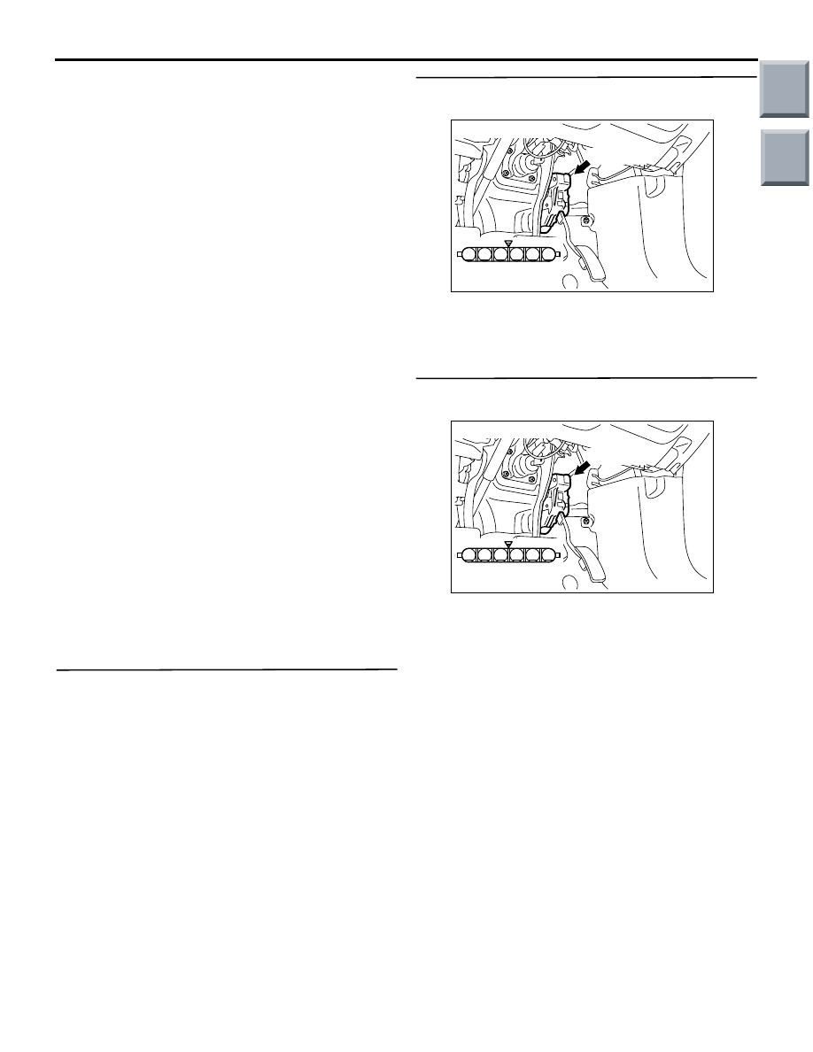
STEP 2. Connector check: B-26 accelerator pedal
position sensor connector
Q: Is the check result normal?
YES :
Go to Step 3.
NO :
Repair or replace.
STEP 3. Perform voltage measurement at B-26
accelerator pedal position sensor connector.
• Disconnect connector, and measure at harness
side.
• Ignition switch: ON
• Voltage between terminal No. 1 and earth.
OK: 4.9
− 5.1 V
Q: Is the check result normal?
YES :
Go to Step 7 .
NO :
Go to Step 4 .
AK402092
1
6 5 4 3 2
B-26(B)
AC
Connector: B-26
Harness side
connector
AK402092
1
6 5 4 3 2
B-26(B)
AC
Connector: B-26
Harness side
connector
Main
Index
Group
TOC