Mitsubishi Colt Ralliart. Manual - part 650
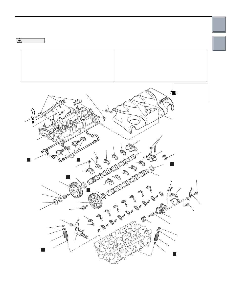
CAMSHAFT AND VALVE STEM SEAL
ENGINE MECHANICAL <4G1>
11C-20
CAMSHAFT AND VALVE STEM SEAL
REMOVAL AND INSTALLATION
M1112006601269
CAUTION
* Remove and assemble the marked parts in each cylinder unit.
Pre-removal Operation
• Air Cleaner Intake Duct, Air Cleaner Assembly and Air
Cleaner Duct Removal (Refer to GROUP 15, Air Cleaner
).
• Valve Timing Belt Removal (Refer to
Post-installation Operation
• Valve Timing Belt Installation (Refer to
• Air Cleaner Intake Duct, Air Cleaner Assembly and Air
Cleaner Duct Installation (Refer to GROUP 15, Air
Cleaner
).
• Drive Belt Tension Check and Adjustment (Refer to
AC402279AE
2
11 ± 1 N·m
3
4
5
7
8
12
9
9.0 ± 2.0 N·m
14 ± 1 N·m
10
13
22 ± 4 N·m
14
15
16
55 ± 5 N·m
88 ± 10 N·m
21 ± 3 N·m
17
18
22
25 ± 1 N·m
20
11 ± 1 N·m
23
21
19
25 ± 1 N·m
25
26
24
27
31
33
34
32
28
30
35
36
37
38*
N
39*
40*
41*
38*
39*
40*
N
42*
N
N
N
N
N
11
5.0 ± 1.0 N·m to 7.0 ± 1.0 N·m
6
5
1
29
When the camshaft
is installed, apply
engine oil on the
sliding parts.
Main
Index
Group
TOC