Mitsubishi Colt Ralliart. Manual - part 640


  Index      Mitsubishi     Mitsubishi Colt Ralliart - service repair manual


Search            


Content   ..  638  639  640  641   ..


Mitsubishi Colt Ralliart. Manual - part 640


TROUBLESHOOTING

ACTIVE STABILITY CONTROL SYSTEM (ASC)

35C-105

Inspection Procedure 11: G and yaw rate sensor power supply circuit
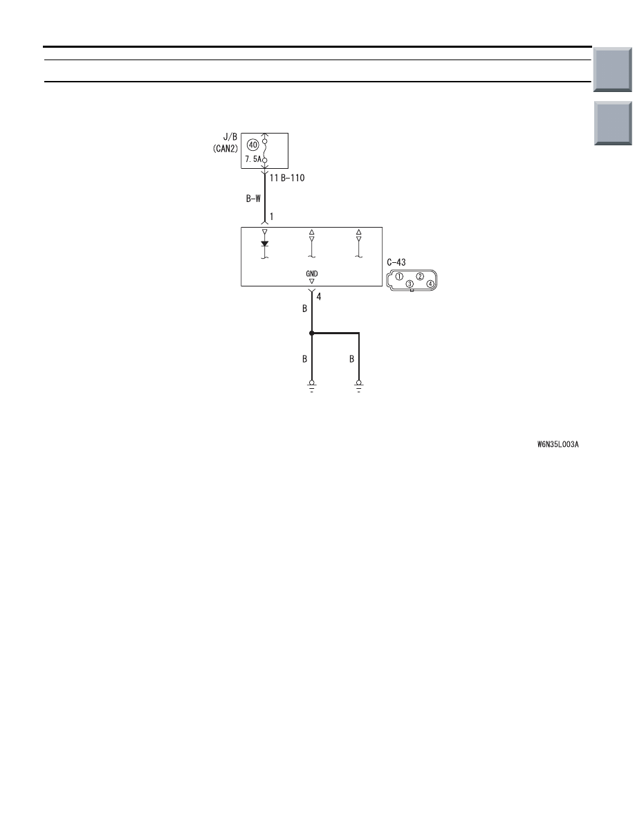
OPERATION

The G and yaw rate sensor is energised by the igni-
tion switch (IG1) through the multi-purpose fuse No. 
40 and the G and yaw rate sensor terminal No. 1.

PROBABLE CAUSES

• Damaged wiring harness and connectors

• G and yaw rate sensor malfunction

G and Yaw Rate Sensor Power Source Circuit

Wire colour code
B : Black     LG : Light green     G : Green     L : Blue     W : White     Y : Yellow     SB : Sky blue
BR : Brown     O : Orange     GR : Grey     R : Red     P : Pink     V : Violet     PU : Purple

G AND 
YAW RATE 
SENSOR

Main

Index

Group

TOC

TROUBLESHOOTING

ACTIVE STABILITY CONTROL SYSTEM (ASC)

35C-106

DIAGNOSTIC PROCEDURE

STEP 1. Connector check: C-45 G and yaw rate 
sensor connector, B-22 Joint connector and 
B-131 junction block connector

Q: Is the check result normal?

YES : 

Go to Step 2.

NO : 

Repair the damaged connector.

STEP 2. Measure the resistance between C-45 G 
and yaw rate sensor connector and B-131 
junction block connector.

(1) Disconnect C-45 G and yaw rate sensor 

connector and connect B-131 junction block 
connector.

(2) Resistance between C-45 G and yaw rate sensor 

connector terminal No. 1 and B-131 junction 
block connector terminal No. 30

OK: Continuity exists (2 

 or less)

AC601093

Connector: C-45

AC

C-45(Black)

Harness side

AC601112

Connector: B-22

AB

B-22

Harness side

J/B

i

û

j

AC601113

J/B

(Back view)

AC601113

Connector: B-131

AB

B-131

Harness side

AC601093

Connector: C-45

AC

C-45(Black)

Harness side

J/B

i

û

j

AC601113

J/B

(Back view)

AC601113

Connector: B-131

AB

B-131

Harness side

AC314017

AC314017AD

Test
harness

B-210 connector:
Harness side

Test
harness

C-26 connector:
Harness side

Main

Index

Group

TOC

TROUBLESHOOTING

ACTIVE STABILITY CONTROL SYSTEM (ASC)

35C-107

Q: Is the check result normal?

YES : 

Go to Step 4.

NO : 

Go to Step 3.

STEP 3. Check the wiring harness between B-129 
junction block connector terminal No. 3 and the 
ignition switch (IG1).

• Check the power supply line for open circuit.

Q: Is the check result normal?

YES : 

Intermittent malfunction (Refer to GROUP 

00 

− How to Cope with Intermittent 

Malfunction 

P.00-13

.)

NO : 

Repair the wiring harness.

STEP 4. Measure the resistance at C-45 G and 
yaw rate sensor connector.

(1) Disconnect C-45 G and yaw rate sensor 

connector, and measure at the harness side.

(2) Resistance between C-45 G and yaw rate sensor 

connector terminal No. 4 and the body earth

OK: Continuity exists (2 

 or less)

Q: Is the check result normal?

YES : 

Go to Step 6.

NO : 

Go to Step 5.

STEP 5. Check the harness wire between C-45 G 
and yaw rate sensor connector terminal No. 4 
and the body earth.

• Check the earth wires for open circuit.

Q: Is the check result normal?

YES : 

Intermittent malfunction (Refer to GROUP 

00 

− How to Cope with Intermittent 

Malfunction 

P.00-13

.)

NO : 

Repair the wiring harness.

J/B

i

û

j

AC601113

J/B

(Back view)

AC601113

Connector: B-129

AC

B-129

Harness side

AC601114

Connector: B-141

AD

B-141

Harness side

AC601093

Connector: C-45

AC

C-45(Black)

Harness side

AC313977AM

C-26 Harness 
connector:
Harness side

Test
harness

AC601093

Connector: C-45

AC

C-45(Black)

Harness side

Main

Index

Group

TOC

TROUBLESHOOTING

ACTIVE STABILITY CONTROL SYSTEM (ASC)

35C-108

STEP 6. System retest
Check that the G and yaw rate sensor communicates 
with the ASC-ECU normally.
NOTE: When the G and yaw rate sensor related 
diagnosis code is not set to ASC-ECU and the G and 
yaw rate sensor is not indicated in red at the 
M.U.T.-III CAN bus diagnosis, the communication 
with the G and yaw rate sensor is normal.

Q: Is the check result normal?

YES : . 

Intermittent malfunction (Refer to GROUP 

00 

− How to Cope with Intermittent 

Malfunction 

P.00-13

.)

NO : . 

Replace the G and yaw rate sensor.

Main

Index

Group

TOC


Content   ..  638  639  640  641   ..