Mitsubishi Colt Ralliart. Manual - part 638
TROUBLESHOOTING
ACTIVE STABILITY CONTROL SYSTEM (ASC)
35C-97
COMMENTS ON TROUBLE SYMPTOM
• The brake warning lamp drive signal at the EBD
system error and the low brake fluid level is sent
from the ASC-ECU to the combination meter
through the CAN communication lines.
• If the combination meter detects a ASC time-out
due to a failure in the power supply to the
ASC-ECU or abnormal CAN communication, the
combination meter illuminates the lamp.
• The ASC-ECU sends the lamp drive signal to the
combination meter during a bulb check (for three
seconds after the ignition switch is turned on)
through the CAN communication lines, and then
the combination meter activates the lamp.
• If the combination meter detects a ASC time-out
due to a failure in abnormal CAN communication,
the combination meter illuminates the lamp.
• This symptom appears when the brake fluid level
switch or the parking brake switch is shorted to
earth. When the brake fluid level witch is shorted
to earth, the diagnosis code No. C1345 is set.
PROBABLE CAUSES
• Damaged wiring harness and connectors
• Parking brake switch malfunction
• Brake fluid level switch malfunction
• Combination meter assembly malfunction
• ASC-ECU malfunction
DIAGNOSTIC PROCEDURE
STEP 1. Check the brake fluid level.
Check that the brake fluid is filled to the specified.
Q: Is the check result normal?
YES :
Check the brake pad remaining thickness,
fill the brake fluid to the specified, and then
go to Step 12.
NO :
Go to Step 2.
STEP 2. M.U.T.-III data list
Using the data list, check that the parking brake input
signal and the brake fluid level switch signal are nor-
mal.(Refer to
.)
• Item No. 28: Side brake switch
• Item No. 32: Brake fluid level switch
Q: Is the check result normal?
YES :
Go to Step 10.
NO :
Go to Step 3.
STEP 3. Check the brake fluid level switch as a
single unit.
Refer to GROUP 35A
− On-vehicle Service
Q: Is the check result normal?
YES :
Go to Step 4.
NO :
Replace the reservoir assembly. (Refer to
GROUP 35A
− Master cylinder assembly
and brake booster
STEP 4. Check A-03 brake fluid level switch
connector and A-05 ASC-ECU connector.
Q: Is the check result normal?
YES :
Go to Step 5.
NO :
Repair the A-03 brake fluid level switch
connector and the A-05 ASC-ECU
connector.
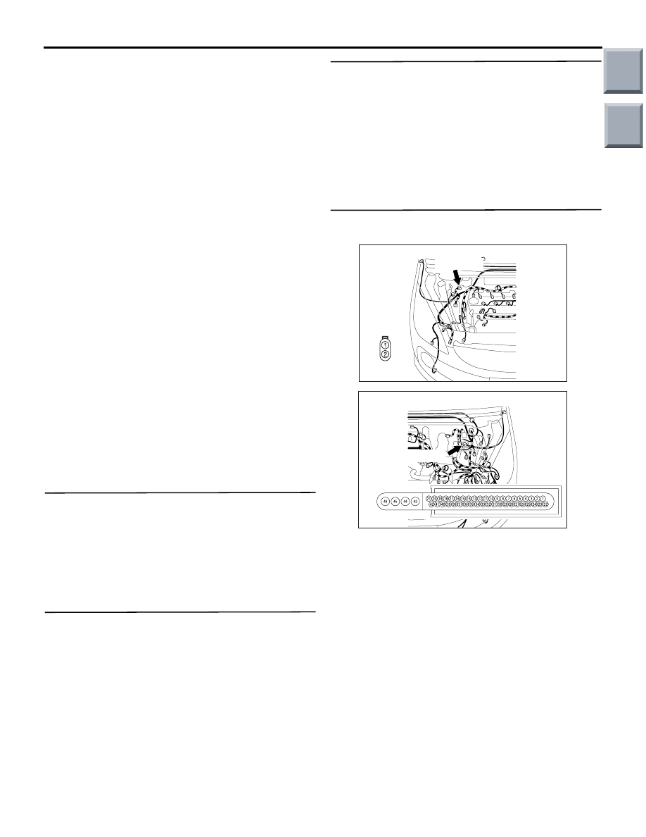
AC601084
Connector: A-03
AD
A-03(Grey)
Harness
side
AC601083
Connector: A-05
AB
A-05(Black)
Harness side
Main
Index
Group
TOC