Mitsubishi Colt Ralliart. Manual - part 637


  Index      Mitsubishi     Mitsubishi Colt Ralliart - service repair manual


Search            


Content   ..  635  636  637  638   ..


Mitsubishi Colt Ralliart. Manual - part 637


TROUBLESHOOTING

ACTIVE STABILITY CONTROL SYSTEM (ASC)

35C-93

STEP 3. Check the parking brake switch as single 
unit.
Refer to GROUP 36 

 On-vehicle Service 

P.36-5

.

Q: Is the check result normal?

YES : 

Go to Step 4.

NO : 

Replace the parking brake switch. (Refer to 
GROUP 36 

− Parking brake lever 

P.36-7

.)

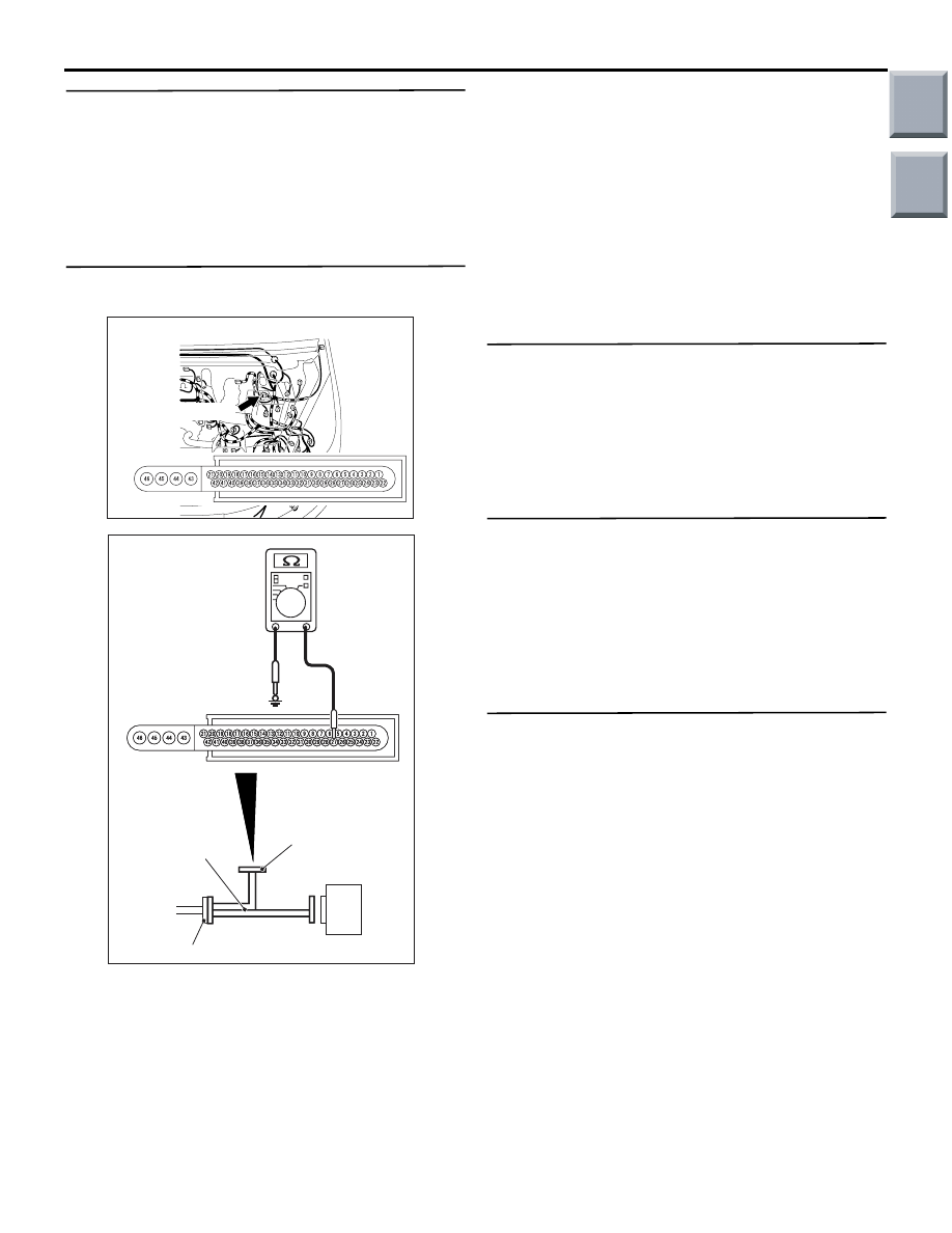
STEP 4. Measure the resistance at A-05 ASC-ECU 
connector.

(1) Disconnect the A-05 ASC-ECU connector, and 

connect the ABS check harness (Special tool: 
MB991984) to the harness side connector.
NOTE: . Do not connect the ABS check harness 
(Special tool: MB991984) to the ASC-ECU.

(2) Pull the parking brake lever and turn the parking 

brake switch to ON. 

(3) Measure the resistance between A-05 ASC-ECU 

connector terminal No. 27 and the body earth.

OK: Continuity exists (2 

 or less)

Q: Is the check result normal?

YES : 

Go to Step 5.

NO : 

Repair the harness wire between A-05 
ASC-ECU connector terminal No. 27 and 
C-44 parking brake switch connector 
terminal No. 1.

STEP 5. Retest the system.

Q: Does the brake warning lamp illuminate when the 

parking brake is operated?
YES : 

Intermittent malfunction (Refer to GROUP 

00 

− How to Cope with Intermittent 

Malfunction 

P.00-13

.)

NO : 

Replace the ASC-ECU.

STEP 6. Retest the system.

Q: Does the brake warning lamp illuminate when the 

parking brake is operated?
YES : 

Intermittent malfunction (Refer to GROUP 

00 

− How to Cope with Intermittent 

Malfunction 

P.00-13

.)

NO : 

Replace the combination meter assembly, 
and then go to Step 7.

STEP 7. Retest the system.

Q: Does the brake warning lamp illuminate when the 

parking brake is operated?
YES : 

This diagnosis is complete.

NO : 

Replace the ASC-ECU.

AC601083

Connector: A-05

AB

A-05(Black)

Harness side

AC601085

AC601085AJ

MB991984

ASC-ECU

Check connector

ASC-ECU harness connector

Main

Index

Group

TOC

TROUBLESHOOTING

ACTIVE STABILITY CONTROL SYSTEM (ASC)

35C-94

Inspection Procedure 7: Brake warning lamp does not illuminate when the brake fluid level is low. 
illuminates when the parking brake is operated.)

COMMENTS ON TROUBLE SYMPTOM

• When the brake fluid level is low, the ASC-ECU 

sends the brake warning lamp drive signal to the 
combination meter through the CAN communica-
tion lines.

• The ASC-ECU sends the lamp drive signal to the 

combination meter during a bulb check (for three 
seconds after the ignition switch is turned on) 
through the CAN communication lines, and then 
the combination meter activates the lamp.

• If the combination meter detects a ASC time-out 

due to a failure in abnormal CAN communication, 
the combination meter illuminates the lamp.

PROBABLE CAUSES

• Damaged wiring harness and connectors

• Brake fluid level switch malfunction

• Combination meter assembly malfunction

• ASC-ECU malfunction

DIAGNOSTIC PROCEDURE

STEP 1. M.U.T.-III data list
Using the data list, check that the brake fluid level 
switch signal is normal.(Refer to 

P.35C-109

.)

• Item No. 32: Brake fluid level switch

Q: Is the check result normal?

YES : 

Go to Step 6.

NO : 

Go to Step 2.

Brake Fluid Level Switch Circuit

Wire colour code
B : Black     LG : Light green
G : Green     L : Blue      
W : White     Y : Yellow
SB : Sky blue     BR : Brown 
O : Orange     GR : Grey  
R : Red     P : Pink     
V : Violet     PU : Purple

ASC-ECU

BRAKE 
FLUID 
LEVEL 
SWITCH

(EARTH 7)

Main

Index

Group

TOC

TROUBLESHOOTING

ACTIVE STABILITY CONTROL SYSTEM (ASC)

35C-95

STEP 2. Check A-03 brake fluid level switch 
connector and A-05 ASC-ECU connector.

Q: Is the check result normal?

YES : 

Go to Step 3.

NO : 

Repair.

STEP 3. Check the brake fluid level switch as a 
single unit.
Refer to GROUP 35A 

− On-vehicle Service 

P.35A-11

.

Q: Is the check result normal?

YES : 

Go to Step 4.

NO : 

Replace the reservoir assembly. (Refer to 
GROUP 35A 

− Master cylinder assembly 

and brake booster 

P.35A-23

.)

STEP 4. Measure the resistance at A-03 brake 
fluid level switch connector and A-05 ASC-ECU 
connector.

(1) Disconnect A-03 brake fluid level switch 

connector and A-05 ASC-ECU connector.

(2) Make the brake fluid below the specified level, 

and turn ON the brake fluid level switch.

(3) Measure the resistance between A-03 brake fluid 

level switch connector terminal No. 2 and A-05 
ASC-ECU connector terminal No. 32.

OK: Continuity exists (2 

 or less)

Q: Is the check result normal?

YES : 

Go to Step 5.

NO : 

Repair the harness wire between A-03 
brake fluid level switch connector terminal 
No. 2 and A-05 ASC-ECU connector 
terminal No. 32.

AC601084

Connector: A-03

AD

A-03(Grey)

Harness 
side

AC601083

Connector: A-05

AB

A-05(Black)

Harness side

AC601110

Connector: A-03, A-05

A-05
(Black)

A-03(Grey)

AB

A-03: Harness side

A-05: Harness side

Main

Index

Group

TOC

TROUBLESHOOTING

ACTIVE STABILITY CONTROL SYSTEM (ASC)

35C-96

STEP 5. Measure the resistance at A-03 brake 
fluid level switch connector.

(1) Disconnect A-03 brake fluid level switch 

connector.

(2) Measure the resistance between A-03 brake fluid 

level switch connector terminal No. 2 and the 
body earth.

OK: Continuity exists (2 

 or less)

Q: Is the check result normal?

YES : 

Go to Step 8.

NO : 

Repair the harness wire between A-03 
brake fluid level switch connector terminal 
No. 2 and body earth.

STEP 6. Retest the system.

Q: Does the brake warning lamp illuminate when the 

brake fluid level is low?
YES : 

Intermittent malfunction (Refer to GROUP 

00 

− How to Cope with Intermittent 

Malfunction 

P.00-13

.)

NO : 

Replace the combination meter assembly, 
and then go to Step 7.

STEP 7. Retest the system.

Q: Does the brake warning lamp illuminate when the 

brake fluid level is low?
YES : 

This diagnosis is complete.

NO : 

Replace the ASC-ECU.

STEP 8. Retest the system.

Q: Does the brake warning lamp illuminate when the 

brake fluid level is low?
YES : 

Intermittent malfunction (Refer to GROUP 

00 

− How to Cope with Intermittent 

Malfunction 

P.00-13

.)

NO : 

Replace the ASC-ECU.

Inspection Procedure 8: Brake warning lamp does not extinguish when the ignition switch is ON. 
(Always illuminates)

AC601084

Connector: A-03

AE

A-03(Grey)

Harness side

Brake Fluid Level Switch and Parking Brake Switch Circuit

Wire colour code
B : Black     LG : Light green
G : Green     L : Blue      
W : White     Y : Yellow
SB : Sky blue     BR : Brown 
O : Orange     GR : Grey  
R : Red     P : Pink     
V : Violet     PU : Purple

ASC-ECU

BRAKE 
FLUID 
LEVEL 
SWITCH

(EARTH 7)

PARKING 
BRAKE 
SWITCH

Main

Index

Group

TOC


Content   ..  635  636  637  638   ..