Mitsubishi Colt Ralliart. Manual - part 610


  Index      Mitsubishi     Mitsubishi Colt Ralliart - service repair manual


Search            


Content   ..  608  609  610  611   ..


Mitsubishi Colt Ralliart. Manual - part 610


OIL PAN AND OIL PUMP

ENGINE OVERHAUL <4G1>

11D-40

REMOVAL SERVICE POINT
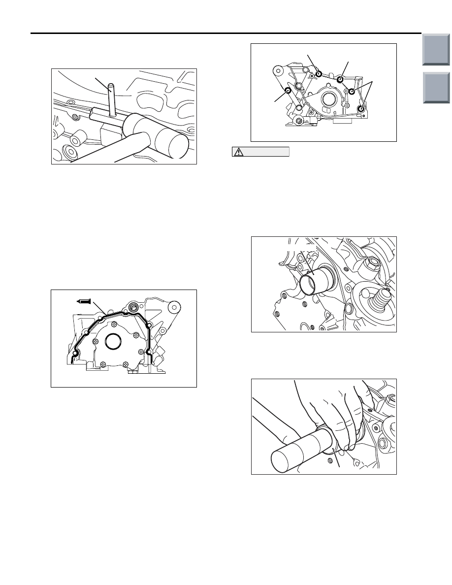
<<A>> OIL PAN REMOVAL

AK201793AC

MD998727

1. Remove the oil pan mounting bolts.
2. Knock the special tool Oil pan remover 

(MD998727) between the oil pan and cylinder 
block as shown in the illustration.

3. Tapping the side of the special tool, slide the tool 

along the oil pan/cylinder block seal and thus 
remove the oil pan.

INSTALLATION SERVICE POINTS
>>A<< OIL PUMP CASE INSTALLATION

AK401834AC

1. Completely remove existing form-in-place gasket 

from the cylinder block (oil pump case mounting 
surface) and oil pump case.

2. Apply a 3 

± 1 mm bead of form-in-place gasket to 

the oil pump case at the positions shown in the 
illustration.

Specified sealant:

Mitsubishi Genuine Part No. 970389 or equiva-

lent

AK401833 AC

M8 × 50

M8 × 30

M8 × 20

M8 × 32

CAUTION

The mounting bolts are different in length. Take 
care not to use wrong bolts in wrong places.
3. Install the oil pump case to the cylinder head, and 

tighten mounting bolts to a specified torque of 14 
± 1 N⋅m.

>>B<< FRONT OIL SEAL INSTALLATION

AK201796AC

MB991962

1. Place the special tool Crankshaft front oil seal 

guide (MB991962) on the crankshaft's front end 
and apply engine oil to the its outer 
circumference.

AK201797AC

MD998306

2. Apply engine oil to the oil seal lip, then push the 

oil seal along the guide by hand until it touches 
the front case. Tap the oil seal into place using the 
special tool Camshaft oil seal installer 
(MD998306).

Main

Index

Group

TOC

OIL PAN AND OIL PUMP

ENGINE OVERHAUL <4G1>

11D-41

>>C<< OIL PAN INSTALLATION

AK201872

1. Completely remove existing form-in-place gasket 

from the cylinder block (oil pan mounting surface) 
and oil pan.

2. Apply a 4 

± 1mm bead of form-in-place gasket to 

the oil pan at the positions shown in the 
illustration.

Specified sealant:

Mitsubishi Genuine Part No. 970389 or equiva-

lent

3. Install the oil pan to the cylinder block and tighten 

the tightening bolt to the specified torque of 7.0 

± 

1.0 N

⋅m.

>>D<< DRAIN PLUG GASKET 
INSTALLATION

AK300601AB

Drain plug

Oil pan

Gasket

Oil pan 
side

CAUTION

Installing the gasket with the wrong side facing 
the oil pan will result in oil leakage.
Replace the drain plug gasket with a new one. Install 
it with the side indicated in the illustration toward the 
oil pan.

>>E<< OIL PRESSURE SWITCH 
INSTALLATION

AK402699

1 mm

5 mm

AB

CAUTION

The threaded part tip of the switch must be clear 
of the sealant.
1. Completely remove existing sealant from the oil 

pressure switch and the switch mounting hole on 
the oil pump case.

Main

Index

Group

TOC

OIL PAN AND OIL PUMP

ENGINE OVERHAUL <4G1>

11D-42

2. Apply specified sealant to the threaded part of the 

oil pressure switch as shown.

Specified sealant:

LOCTITE 565 or equivalent

3. Install the oil pressure switch to the oil pump case 

by tightening to a specified torque of 10 

± 2 N⋅m.

>>F<< OIL FILTER INSTALLATION

AK103810

1. Clean the filter mounting surface on the front 

case.

2. Apply engine oil to the O-ring of the oil filter.

AK201798AC

CAUTION

If the filter is tightened by hand only, it will be 
insufficiently torqued, resulting in oil leaks.
3. Screw the oil filter in and tighten the oil filter to the 

specified torque using a commercially available 
filter wrench from where the O-ring has come into 
contact with the oil filter mounting surface.

Specified torque:

MD348631, MD365876 16 

± 4 Nm (approx. 3/4 

of a turn)

MD360935 14 

± 2 Nm (approx. 1 turn)

INSPECTION

M1113008200502

OIL PUMP

1. Fit the inner rotor and the outer rotor into the oil 

pump case.

AK201799

2. Check the tip clearance using a thickness gauge.

Standard value: 0.06 

 0.18 mm

AK201800

3. Check the side clearance using a straight edge 

and thickness gauge.

Standard value: 0.10 

 0.18 mm

AK201801

4. Check the body clearance using a thickness 

gauge.

Standard value: 0.040 

 0.095 mm

Main

Index

Group

TOC

PISTON AND CONNECTING ROD

ENGINE OVERHAUL <4G1>

11D-43

PISTON AND CONNECTING ROD

REMOVAL AND INSTALLATION

M1113008401123

AK202375AC

Apply engine oil to 
all moving parts 
before installation.

5

11

9

6

7

8

10

12

4

3

2

1

17 ± 2 N·m + 90˚ to 94˚

Removal steps 

>>

G

<<1. Connecting rod nut

<<

A

>> >>

F

<< 2. Connecting rod cap

>>

E

<< 3. Connecting rod bearing

>>

D

<< 4. Piston and connecting rod assembly

5. Connecting rod bearing

>>

C

<< 6. Piston ring No. 1

>>

C

<< 7. Piston ring No. 2

>>

B

<< 8. Oil ring

<<

B

>> >>

A

<< 9. Piston pin

10. Piston
11. Connecting rod
12. Bolt

Removal steps (Continued)

Main

Index

Group

TOC


Content   ..  608  609  610  611   ..