Mitsubishi Colt Ralliart. Manual - part 607


  Index      Mitsubishi     Mitsubishi Colt Ralliart - service repair manual


Search            


Content   ..  605  606  607  608   ..


Mitsubishi Colt Ralliart. Manual - part 607


ROCKER ARMS AND CAMSHAFT

ENGINE OVERHAUL <4G1>

11D-28

REMOVAL SERVICE POINTS
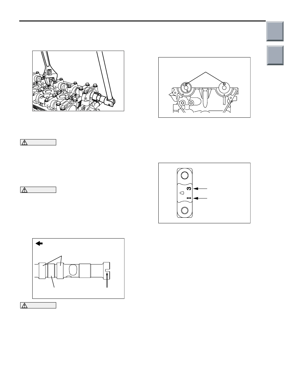
<<A>> CAM POSITION SENSING CYLIN-
DER REMOVAL

AK201784

Holding the hexagonal portion of the camshaft with a 
wrench, remove the cam position sensing cylinder.

<<B>> LASH ADJUSTER REMOVAL

CAUTION

If the lash adjuster is to be reused, be sure to 
clean and inspect it before installation. (Refer 
to

P.11D-30

.) 

INSTALLATION SERVICE POINTS
>>A<< LASH ADJUSTER INSTALLATION

CAUTION

If the lash adjuster is to be reused, be sure to 
clean and inspect it before installation. (Refer 
to

P.11D-30

.)

While using care not to spill diesel fuel in the lash 
adjuster, install the lash adjuster on the rocker arm.

>>B<< CAMSHAFT INSTALLATION

AK201833 AC

Timing belt side

Journal

Cam

Slit

CAUTION

• Do not confuse intake and exhaust cam-

shafts.

• A 4 mm slit is on the rear end of the intake 

camshaft.

Apply engine oil to the camshaft journal and cams 
before installation.

>>C<< FRONT BEARING CAP/BEARING 
CAP/REAR RIGHT BERING CAP/REAR 
LEFT BEARING CAP INSTALLATION

AK201834AC

Dowel pin

1. Place the dowel pins of the camshafts in the 

positions shown in the illustration.
NOTE: By getting the dowel pins into position 
shown in the illustration, the camshaft slots of 
tightening the cylinder head bolt are put in posi-
tion.

AK201835AC

Cap No.

Identification mark 
for intake/exhaust side

2. The bearing caps No. 2 to 5 are identical in shape. 

Before installation, be sure to check the cap 
numbers and identification marks so that right 
bearing caps are installed in right places.

Identification marks (Die-stamped on front 

and No. 2 to 5 bearing caps)

I: Intake side
E: Exhaust side

3. Completely remove existing sealant from the 

bearing caps and cylinder head.

Main

Index

Group

TOC

AK201836AC

Timing belt side

ROCKER ARMS AND CAMSHAFT

ENGINE OVERHAUL <4G1>

11D-29

4. Apply specified sealant to the cylinder head at the 

points shown in the illustration.

Specified sealant:

3M ATD No.8660 or equivalent

5. Install the bearing caps in position and tighten 

bolts increasingly by giving turns 2 to 3 times 
each.
NOTE: Completely wipe off excess of applied 
sealant that comes out.

6. Finally, tighten the bearing cap bolts to a specified 

torque.

Specified torque

Front bearing cap: 21 

± 2 Nm

Bearing cap: 11 

± 1 Nm

Rear right bearing cap: 21 

± 2 Nm

Rear left bearing cap: 21 

± 2 Nm

7. Check that the rocker arms are installed in 

position.

>>D<< CAM POSITION SENSING 
CYLINDER INSTALLATION

AK201785

Holding the hexagonal portion of the camshaft, 
tighten the cam position sensing cylinder to a speci-
fied torque of 22 

± 4 N⋅m.

>>E<< CIRCULAR PACKING 
INSTALLATION

AK201783AC

MD998762

Using the special tool Circular packing installer 
(MD998762), install the circular packing into the cyl-
inder head.

>>F<< OIL SEAL INSTALLATION

AK201782

MD998713

AC

Using the special tool Oil seal installer (MD998713), 
install the oil seal into the cylinder head.

>>G<< OIL FEEDER CONTROL VALVE 
FILTER INSTALLATION

CAUTION

Check the filter for foreign matters, damage and 
deformation before installation.

>>H<< OIL FEEDER CONTROL VALVE 
INSTALLATION

1. Apply a small amount of engine oil to the o-ring of 

the oil feeder control valve.

2. Install the oil feeder control valve to the cylinder 

head.

3. Tighten the oil feeder control valve bolt to the 

specified torque of 11 

± 1 N⋅m.

Main

Index

Group

TOC

ROCKER ARMS AND CAMSHAFT

ENGINE OVERHAUL <4G1>

11D-30

INSPECTION

M1113005500838

CAMSHAFT

AK201786

Measure the cam height (nose-to-heel diameter).
If any cam is worn beyond the limit, replace the cam-
shaft.

Standard values: 

Intake 35.08 mm
Exhaust 34.26 mm

Limit: 

Intake 34.58 mm
Exhaust 33.76 mm

LASH ADJUSTERS

CAUTION

• The lash adjuster is a precision-engineered 

component. Do not allow dust or other for-
eign matter to enter it.

• Do not disassemble lash adjusters.

AK202836

A

B

C

For rough 
cleaning

For finish 
cleaning

For diesel 
fuel filling

AB

Use only non-contaminated diesel fuel to 
clean the lash adjuster.

1. Prepare three containers and approximately five 

liters of diesel fuel. Pour into each container the 
diesel fuel in an amount enough for a lash 
adjuster placed in the container in its upright 
position to completely submerge.

AK202837

Diesel fuel

AC

2. Place the lash adjuster in container A and wash 

its outside surface.
NOTE: Use a nylon brush if there are 
hard-to-remove deposits.

AK202839

MD998442

AB

Diesel fuel

CAUTION

The steel ball spring of the lash adjuster is 
extremely weak. The lash adjuster's functionality 
may be badly affected if the special tool is 
inserted too strongly.
3. While gently pushing the internal steel ball using 

the special tool Air bleed wire (MD998442), move 
the plunger in and out 5 

− 10 times to eliminate 

stiffness in the plunger and expel contaminated 
oil.
NOTE: The plunger must be free from jamming 
and any other abnormalities. If a defect is found in 
plunger operation, replace the lash adjuster.

AK202840

Diesel fuel

MD998442

AB

Main

Index

Group

TOC

ROCKER ARMS AND CAMSHAFT

ENGINE OVERHAUL <4G1>

11D-31

CAUTION

The hole in the side of the lash adjuster must be 
directed toward the inside of container A. Never 
direct it against any person.
4. Take the lash adjuster out of the container, then 

move the plunger by pushing the steel ball gently 
to discharge the diesel fuel from the pressure 
chamber.

AK202839

MD998442

AB

Diesel fuel

CAUTION

The steel ball spring of the lash adjuster is 
extremely weak. The lash adjuster's functionality 
may be badly affected if the special tool is 
inserted too strongly.
5. Soak the lash adjuster in the diesel fuel in 

container B. Move the plunger in and out 5 

− 10 

times by gently pushing the internal steel ball 
using the special tool Air bleed wire (MD998442) 
until the plunger moves smoothly to wash the lash 
adjuster’s pressure chamber.

AK202840

Diesel fuel

MD998442

AB

CAUTION

The hole in the side of the lash adjuster must be 
directed toward the inside of container B. Never 
direct it against any person.
6. Take the lash adjuster out of the container, then 

move the plunger by pushing the steel ball gently 
to discharge the diesel fuel from the pressure 
chamber.

AK202841

Diesel fuel

MD998442

AB

CAUTION

Do not use container C for cleaning. If cleaning is 
performed in container C, foreign matter could 
enter the pressure chamber when the chamber is 
filled with diesel fuel.
7. Soak the lash adjuster in the diesel fuel in 

container C. Gently push the internal steel ball 
using the special tool Air bleed wire (MD998442).

AK202842

Diesel fuel

MD998442

AB

8. Place the lash adjuster upright with the plunger at 

the top. Push the plunger firmly until it makes a 
full stroke, then return the plunger slowly and 
release the hold of the steel ball to allow the 
pressure chamber to be filled with diesel fuel.

AK202843

9. Take the lash adjuster out of the container, place it 

upright with the plunger at the top, and push the 
plunger firmly. The plunger must not move at all.

Main

Index

Group

TOC


Content   ..  605  606  607  608   ..