Mitsubishi Colt Ralliart. Manual - part 603


  Index      Mitsubishi     Mitsubishi Colt Ralliart - service repair manual


Search            


Content   ..  601  602  603  604   ..


Mitsubishi Colt Ralliart. Manual - part 603


TIMING BELT

ENGINE OVERHAUL <4G1>

11D-12

TIMING BELT

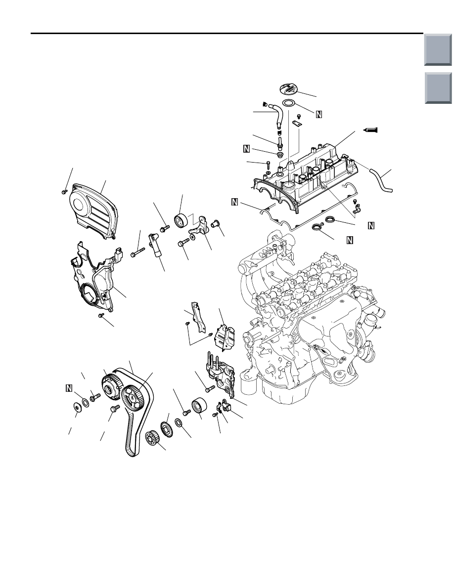
REMOVAL AND INSTALLATION

M1113001901387

AK600556AC

1

11 ± 1 N·m

11 ± 1 N·m

2

7

6

5

4

3

24

12

9

10

11

8

14

16

15

17

28

20

18

23

21

27

13

25

30

29

36 ± 6 N·m

44 ± 10 N·m

21 ± 3 N·m

88 ± 10 N·m

22

9.8 ± 2.0 N·m

48 ± 6 N·m

48 ± 6 N·m

23 ± 3 N·m

55 ± 5 N·m

11 ± 1 N·m

19

26

5.0 ± 1.0 N·m 

→ 7.0 ± 1.0 N·m

Removal steps 

1. Timing belt front upper cover
2. Timing belt front lower cover
3. Breather hose
4. PCV hose
5. PCV valve
6. PCV valve gasket
7. Oil filler cap

>>

H

<< 8. Rocker cover

9. Rocker cover gasket A
10. Rocker cover gasket B

11. Rocker cover gasket C

<<

A

>> >>

G

<< 12. Plug cap

<<

B

>> >>

F

<< 13. Timing belt

>>

E

<< 14. Tensioner pulley

15. Tensioner arm
16. Shaft

>>

D

<< 17. Auto-tensioner

18. Idler pulley
19. Bracket
20. Crank angle sensor

Removal steps (Continued)

Main

Index

Group

TOC

TIMING BELT

ENGINE OVERHAUL <4G1>

11D-13

CAUTION

Never disassemble the V.V.T. sprocket.

REMOVAL SERVICE POINTS
<<A>> PLUG CAP REMOVAL

AK201770

Remove the plug cap using a wrench fitted on the 
hexagonal portion of the camshaft.

<<B>> TIMING BELT REMOVAL

1. By turning the crankshaft, position the No.1 

cylinder at the Top Dead Center of the 
compression stroke.

AK201771AC

2. If the timing belt is to be reused, it is necessary to 

install it in the same direction as it was before. 
Mark an arrow that shows the direction of rotation 
on the back surface of the timing belt with chalk, 
etc.

<<C>> V.V.T. SPROCKET BOLT REMOVAL

AK201772

Remove the V.V.T. sprocket bolt using a wrench fitted 
on the hexagonal portion of the camshaft.

<<D>> CAMSHAFT SPROCKET BOLT 
REMOVAL

AK201773

Remove the camshaft sprocket bolt using a wrench 
fitted on the hexagonal portion of the camshaft.

>>

C

<< 21. Crankshaft sprocket

>>

C

<< 22. Spacer

>>

C

<< 23. Sensing blade

<<

C

>> >>

B

<< 24. V.V.T. sprocket bolt

>>

B

<< 25. V.V.T. sprocket

<<

D

>> >>

A

<< 26. Camshaft sprocket bolt

27. Camshaft sprocket
28. Engine support bracket
29. Timing belt rear cover, right
30. Timing belt rear cover, left

Removal steps (Continued)

Main

Index

Group

TOC

TIMING BELT

ENGINE OVERHAUL <4G1>

11D-14

INSTALLATION SERVICE POINTS
>>A<< CAMSHAFT SPROCKET BOLT 
INSTALLATION

AK201774

Tighten the camshaft sprocket bolt to 88 

± 10 N⋅m 

while preventing the camshaft from rotation using a 
wrench fitted on the hexagonal portion of the cam-
shaft.

>>B<< V.V.T. SPROCKET BOLT/V.V.T. 
SPROCKET INSTALLATION

AK201820AC

V.V.T. 
sprocket 
bolt

V.V.T. sprocket

Camshaft

1. Apply a proper minimum quantity of engine oil to 

the following points.

• Camshaft end

• Insertion hole in V.V.T. sprocket (all over inside 

and outside surfaces)

• Threads and head of V.V.T. sprocket bolt

• Bearing surface of V.V.T. sprocket bolt

2. Install the V.V.T. sprocket onto the camshaft.
3. Make sure that the V.V.T. sprocket is installed all 

the way onto the camshaft. Holding the hexagonal 
portion of the camshaft with a wrench, check that 
the V.V.T. sprocket does not turn. 

AK201775

4. Holding the hexagonal portion of the camshaft 

with a wrench, tighten the V.V.T. sprocket bolt to a 
specified torque of 55 

± 5 N⋅m.

5. Holding the hexagonal portion of the camshaft 

with a wrench, check that the V.V.T. sprocket is 
not loose to turn.
NOTE: This check is to ascertain that the V.V.T. 
sprocket is locked at the most retarding position 
by means of internal pin.

>>C<< CRANKSHAFT 
SPROCKET/SPACER/SENSING BLADE 
INSTALLATION

AK201823AC

Degrease

Oil pump case

Clean

Spacer

Sensing blade

Crankshaft sprocket

Crankshaft

1. Clean the hole in the crankshaft sprocket.
2. Clean and degrease the mating surfaces of the 

crankshaft sprocket and spacer; sensing blade; 
crankshaft sprocket; and oil pump case.
NOTE: Degreasing is necessary to prevent 
decrease in friction between the mating surfaces 
due to presence of oil.

Main

Index

Group

TOC

AK201824

AK201824AD

Backside

Slot

TIMING BELT

ENGINE OVERHAUL <4G1>

11D-15

3. Assemble the crankshaft sprocket and sensing 

blade, projection to slot, as shown.

AK600560AB

Pin

Pin hole

4. Align the pins to the pin holes and apply even 

pressure in the arrow direction.

CAUTION

When installing the sprocket, do not bend the 
sensing blade.
5. Install the crankshaft sprocket onto the 

crankshaft.

>>D<< AUTO-TENSIONER INSTALLATION

AK201880AC

A

B

1. If the auto-tensioner rod remains in its fully 

extended position, reset it to the retracted position 
as follows:
(1) Clamp the auto-tensioner in a vise at right 

angles to the jaws.

CAUTION

Because the leak down of the auto-tensioner 
takes a long time, slowly insert the rod. If the rod 
is suddenly inserted, the auto-tensioner could be 
damaged.

(2) Push in the rod little by little with the vise until 

the set hole A in the rod is aligned with the set 
hole B in the cylinder.

AK300154

(3) Insert a piece of wire (1.4 mm diameter) into 

the set holes.

(4) Remove the auto-tensioner from the vise.

2. Install the auto-tensioner in position. Leave the 

wire installed until the auto-tensioner is 
completely installed.

Main

Index

Group

TOC


Content   ..  601  602  603  604   ..