Mitsubishi Colt Ralliart. Manual - part 601
REWORK DIMENSIONS
ENGINE OVERHAUL <4G1>
11D-4
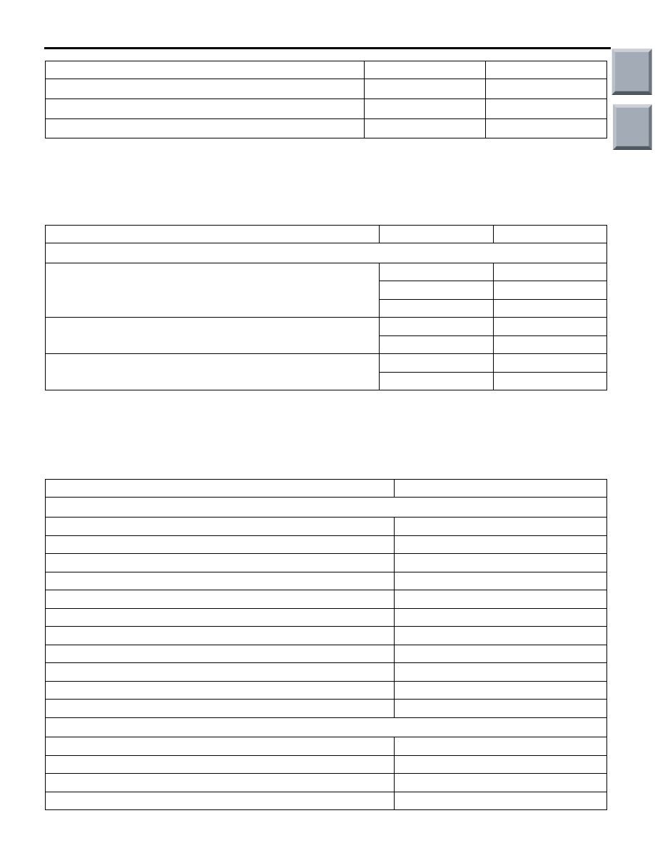
REWORK DIMENSIONS
M1113024300480
Item
Standard value
Standard value
CYLINDER HEAD AND VALVES
Cylinder head oversize valve guide hole diameter mm
0.05 O.S.
10.55
− 10.57
0.25 O.S.
10.75
− 10.77
0.50 O.S.
11.00
− 11.02
Cylinder head oversize valve seat hole diameter, intake mm
0.30 O.S.
31.30
− 31.33
0.60 O.S.
31.60
− 31.63
Cylinder head oversize valve seat hole diameter, exhaust mm
0.30 O.S.
27.80
− 27.82
0.60 O.S.
28.10
− 28.12
TORQUE SPECIFICATIONS
M1113023401777
Cylinder bore diameter mm
75.50
− 75.53
−
Taper of cylinder mm
0.01 or less
−
Cylinder-to-piston clearance mm
0.02
− 0.04
−
Item
Standard value
Limit
Item
N
⋅m
ALTERNATOR AND IGNITION SYSTEM
Oil level gauge guide bolt
24
± 4
Water pump pulley bolts
9.0
± 2.0
Crankshaft bolts
181
Alternator brace bolt (alternator side)
22.5
± 2.5
Alternator brace bolt (tightened with water pump)
24
± 3
Alternator nut
44
± 10
Adjusting bolt
5.0
± 1.0
Ignition coil bolts
10
± 2
Spark plug
25
± 5
Cam position sensor bolt
8.8
± 1.0
Cam position sensor support bolts
14
± 1
TIMING BELT
Timing belt cover bolts
11
± 1
Rocker cover bolts
5.0
± 1.0 → 7.0 ± 1.0
Plug cap
21
± 3
Tensioner pulley bolt
48
± 6
Main
Index
Group
TOC