Mitsubishi Colt Ralliart. Manual - part 552


  Index      Mitsubishi     Mitsubishi Colt Ralliart - service repair manual


Search            


Content   ..  550  551  552  553   ..


Mitsubishi Colt Ralliart. Manual - part 552


TROUBLESHOOTING

SUPPLEMENTAL RESTRAINT SYSTEM (SRS)

52B-46

Q: Is diagnosis code 21 set?

YES : 

Go to Step 6.

NO : 

Replace the clock spring (Refer to 

P.52B-145

).

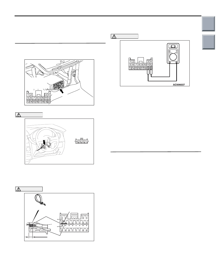
STEP 6. Resistance measurement at the 
SRS-ECU connector B-35.
(1) Disconnect the negative battery terminal.

(2) Disconnect SRS-ECU connector B-35.

DANGER

To prevents the air bag from deploying unin-
tentionally, disconnect the clock spring con-
nector B-136 to short the squib circuit.

(3) Disconnect the clock spring connector B-136.

CAUTION

Insert an insulator such as a cable tie to a depth 
of 4 mm or more, otherwise the short spring will 
not be released.

(4) Insert a cable tie [3 mm wide, 0.5 mm thick] 

between terminals 11, 12 and the short spring to 
release the short spring.

CAUTION

Do not insert a test probe into the terminal from 
its front side directly as the connector contact 
pressure may be weakened.
(5) Resistance measurement between B-35 harness 

side connector terminals 11 and 12.

OK: Open circuit

Q: Is the check result normal? 

YES : 

Go to Step 7.

NO : 

Repair the harness wires between 
SRS-ECU connector B-35 (terminal No.11 
and 12) and clock spring connector B-136 
(terminal No.3 and 4). 

STEP 7. Check whether the diagnosis code is 
reset.

Q: Is diagnosis code 21 set?

YES : 

Replace the SRS-ECU (Refer to 

P.52B-143

).

NO : 

An intermittent malfunction is suspected 
(Refer to GROUP 00, How to Cope with 
Intermittent Malfunctio

P.00-13

).

AC206285

AF

B-35 (Y)

Connector: B-35

Harness side 
connector 
(rear view)
 

AC313828 AF

Connectors: B-136

B-136

Harness side 
connector 
(rear view)
 

AC100391

Section
A - A

B-35 
Harness side connectors
(front view)

Cable tie

Short spring

4 mm or more

Terminal

A

AZ

A

B-35 Harness side connector 
(rear view)

AS

Main

Index

Group

TOC

TROUBLESHOOTING

SUPPLEMENTAL RESTRAINT SYSTEM (SRS)

52B-47

Code No.22: Driver's air bag module (squib) system (open-circuited in the squib circuit)

OPERATION

• The SRS-ECU judges how severe a collision is 

by detecting signals from the front impact sensors 
and the front air bag analogue G-sensor. If the 
impact is over a predetermined level, the 
SRS-ECU sends an ignition signal. At this time, if 
the front air bag safing G-sensor is on, the SRS 
air bag will inflate. 

• The ignition signal is input to the air bag module 

via the clock spring to inflate the air bag.

DIAGNOSIS CODE SET CONDITIONS

This diagnosis code is set if driver’s air bag squib 
wire(s) are open-circuited. However, if no diagnosis 
code resets, the SRS warning lamp will be switched 
off (diagnosis code will be retained). 

PROBABLE CAUSES

• Open circuit in the clock spring

• Open circuit due to improper neutral position of 

the clock spring

• Open circuit in the driver's air bag module (squib) 

circuit

• Disengaged driver's air bag module (squib) con-

nector

• Improper connector contact

• Malfunction of the SRS-ECU

AC510223

Wire colour code
B : Black     LG : Light green     G : Green     L : Blue     W : White     Y : Yellow     SB : Sky blue
BR : Brown     O : Orange     GR : Grey     R : Red     P : Pink     V : Violet

AIR BAG MODULE
(SQUIB)
(DRIVER'S SIDE)

CONNECTOR
LOCK SWITCH

CONNECTOR
LOCK SWITCH

CLOCK 
SPRING

SRS-ECU

CONNECTOR
LOCK SWITCH

NOTE

: CONNECTOR COUPLED: ON 
  CONNECTOR UNCOUPLED: OFF

Driver's Air Bag Module (Squib) Circuit

AB

Main

Index

Group

TOC

TROUBLESHOOTING

SUPPLEMENTAL RESTRAINT SYSTEM (SRS)

52B-48

DIAGNOSIS PROCEDURE

STEP 1. Check the diagnosis code by connecting 
a dummy resistor. (M.U.T.-III diagnosis code)
(1) Disconnect the negative battery terminal.

(2) By sliding the A section (in the figure) of air bag 

module connector B-138 in the arrow direction, 
disconnect the connector.

(3) Connect special tool dummy resistor (MB991865) 

to special tool resistor harness (MB991866).

CAUTION

Do not insert a test probe into the terminal from 
its front side directly as the connector contact 
pressure may be weakened.
(4) Insert special tool (MB991866) into clock spring 

side air bag module connector B-138 by 
backprobing.

(5) Connect the negative battery terminal.

(6) Erase the diagnosis code memory, and check the 

diagnosis code.

Q:  Is diagnosis code 22 set?

YES : 

Go to Step 2.

NO : 

Replace the driver's air bag module (Refer 
to 

P.52B-145

). 

STEP 2. Check the clock spring. (M.U.T.-III 
diagnosis code)
(1) Disconnect the negative battery terminal.

(2) Disconnect the clock spring connector B-136.

(3) Connect special tool dummy resistor (MB991865) 

to special tool resistor harness (MB991866).

CAUTION

Do not insert a test probe into the terminal from 
its front side directly as the connector contact 
pressure may be weakened.
(4) Insert special tool (MB991866) into clock spring 

harness side connector B-136 (terminal No.3 and 
4) by backprobing.

(5) Connect the negative battery terminal.
(6) Erase the diagnosis code memory, and check the 

diagnosis code.

Q: Is diagnosis code 22 set?

YES : 

Go to Step 3.

NO : 

Replace the clock spring (Refer to 

P.52B-145

).

AC105823

AC304700

AC305145AF

A

Steering
wheel

B-138 Air bag 
module connector

AC300945AG

MB991865
(Dummy resistor : 3

Ω)

MB991866
(Resistor harness)

B-138 Air bag 
module
connector

AC313828 AF

Connectors: B-136

B-136

Harness side 
connector 
(rear view)
 

AC300949 AF

MB991865 (Dummy
resistor : 3 

Ω)

MB991866
(Resistor harness)

B-136 Clock spring
connector

(Rear view)

Main

Index

Group

TOC

TROUBLESHOOTING

SUPPLEMENTAL RESTRAINT SYSTEM (SRS)

52B-49

STEP 3. Resistance measurement between the 
SRS-ECU connector B-35 (terminal No.11 and 12) 
and the clock spring connector B-136 (terminal 
No.3 and 4)
(1) Disconnect the negative battery terminal.

(2) Disconnect SRS-ECU connector B-35 and clock 

spring connector B-136.

CAUTION

Do not insert a test probe into the terminal from 
its front side directly as the connector contact 
pressure may be weakened.
(3) Resistance measurement between the following 

terminals. 

• SRS-ECU connector B-35 terminal No.11 and 

the clock spring connector B-136 terminal 
No.3

• SRS-ECU connector B-35 terminal No.12 and 

the clock spring connector B-136 terminal 
No.4

OK: Continuity (Less than 2 

)

Q: Are the check results normal? 

YES : 

Go to Step 4

NO : 

Repair the harness wires between 
SRS-ECU connector B-35 (terminal No.11 
and 12) and clock spring connector B-136 
(terminal No.3 and 4).

STEP 4. Check whether the diagnosis code is 
reset.

Q: Is diagnosis code 22 set?

YES : 

Replace the SRS-ECU (Refer to 

P.52B-143

).

NO : 

An intermittent malfunction is suspected 
(Refer to GROUP 00, How to Cope with 
Intermittent Malfunctio

P.00-13

).

AC206285

AF

B-35 (Y)

Connector: B-35

Harness side 
connector 
(rear view)
 

AC313828 AF

Connectors: B-136

B-136

Harness side 
connector 
(rear view)
 

1 2

AC105924

13 14 15 16 17 18 19 20

5 6 7 8 9 10 11 12

1 2

3 4

4

3

B-35
Harness side 
connector (rear view)

B-136
Harness side 
connector 
(rear view)

AH

Main

Index

Group

TOC


Content   ..  550  551  552  553   ..