Mitsubishi Colt Ralliart. Manual - part 551


  Index      Mitsubishi     Mitsubishi Colt Ralliart - service repair manual


Search            


Content   ..  549  550  551  552   ..


Mitsubishi Colt Ralliart. Manual - part 551


TROUBLESHOOTING

SUPPLEMENTAL RESTRAINT SYSTEM (SRS)

52B-42

STEP 4. Check whether the diagnosis code is 
reset.

Q: Is diagnosis code 4F set?

YES : 

Replace the SRS-ECU (Refer to 

P.52B-143

). 

NO : 

An intermittent malfunction is suspected 
(Refer to GROUP 00, How to Cope with 
Intermittent Malfunction 

P.00-13

).

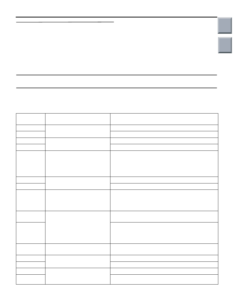
Code No.3C, 3D, 4C, 4D, 14, 15, 16, 17, 31, 32, 45, 51, 52, 54, 55, 56, 57, 58, 59, 73, 74, 83, 84 system 
inside SRS-ECU

DIAGNOSIS CODE SET CONDITIONS

These diagnosis codes are set when a fault is 
detected in the SRS-ECU. The most likely causes for 
this code to be set are shown in the table below:

Code No.

Part/Circuit integral to 
SRS-ECU

Trouble causes

3C

Curtain air bag module (squib) 
(RH) (squib ignition drive circuit)

• Short circuit in the squib ignition drive circuit

3D

• Open circuit in the squib ignition drive circuit

4C

Curtain air bag module (squib) 
(LH) (squib ignition drive circuit)

• Short circuit in the squib ignition drive circuit

4D

• Open circuit in the squib ignition drive circuit

14

Analogue G-sensor

• When the analogue G-sensor is not operating

• When the characteristics of the analogue G-sensor 

are abnormal

• When the output from the analogue G-sensor is 

abnormal

15

Safing G-sensor (for frontal 
collision)

• Short circuit in the safing G-sensor

16

• Open circuit in the safing G-sensor

17

Safing G-sensor (for side 
collision)

• When the safing G-sensor is not operating

• When the characteristics of the safing G-sensor are 

abnormal

• When the output from the safing G-sensor is abnormal

31

Capacitor circuit

• Voltage at the capacitor terminal is higher than the 

specified value for five seconds or more

32

• Voltage at the capacitor terminal is lower than the 

specified value for five seconds or more (This is not 
detected if diagnosis code No.41 or 42 indicating 
battery positive voltage drop has been sent).

45

Non-volatile memory (EEPROM) 
and A/D converter

• When the non-volatile memory (EEPROM) and A/D 

converter system are abnormal

51

Driver's air bag module (squib 
ignition drive circuit)

• Short circuit in the squib ignition drive circuit

52

• Open circuit in the squib ignition drive circuit

54

Passenger's (front) air bag 
module (squib ignition drive 
circuit)

• Short circuit in the squib ignition drive circuit

55

• Open circuit in the squib ignition drive circuit

Main

Index

Group

TOC

TROUBLESHOOTING

SUPPLEMENTAL RESTRAINT SYSTEM (SRS)

52B-43

PROBABLE CAUSE

• Malfunction of the SRS-ECU

DIAGNOSIS

Replace the SRS-ECU (Refer to 

P.52B-143

).

Code No.21: Driver's air bag module (squib) system (short-circuited between terminals of the squib 
circuit)

56

Driver’s seat belt pre-tensioner 
(squib ignition drive circuit)

• Short circuit in the squib ignition drive circuit

57

• Open circuit in the squib ignition drive circuit

58

Passenger’s (front) seat belt 
pre-tensioner (squib ignition drive 
circuit)

• Short circuit in the squib ignition drive circuit

59

• Open circuit in the squib ignition drive circuit

73

Side-airbag module (RH) (squib 
ignition drive circuit)

• Short circuit in the squib ignition drive circuit

74

• Open circuit in the squib ignition drive circuit

83

Side-airbag module (LH) (squib 
ignition drive circuit)

• Short circuit in the squib ignition drive circuit

84

• Open circuit in the squib ignition drive circuit

Code No.

Part/Circuit integral to 
SRS-ECU

Trouble causes

AC510223

Wire colour code
B : Black     LG : Light green     G : Green     L : Blue     W : White     Y : Yellow     SB : Sky blue
BR : Brown     O : Orange     GR : Grey     R : Red     P : Pink     V : Violet

AIR BAG MODULE
(SQUIB)
(DRIVER'S SIDE)

CONNECTOR
LOCK SWITCH

CONNECTOR
LOCK SWITCH

CLOCK 
SPRING

SRS-ECU

CONNECTOR
LOCK SWITCH

NOTE

: CONNECTOR COUPLED: ON 
  CONNECTOR UNCOUPLED: OFF

Driver's Air Bag Module (Squib) Circuit

AB

Main

Index

Group

TOC

TROUBLESHOOTING

SUPPLEMENTAL RESTRAINT SYSTEM (SRS)

52B-44

OPERATION

• The SRS-ECU judges how severe a collision is 

by detecting signals from the front impact sensors 
and the front air bag analogue G-sensor. If the 
impact is over a predetermined level, the 
SRS-ECU sends an ignition signal. At this time, if 
the front air bag safing G-sensor is on, the SRS 
air bag will inflate. 

• The ignition signal is input to the air bag module 

via the clock spring to inflate the air bag.

DIAGNOSIS CODE SET CONDITIONS

This diagnosis code is set if one driver's air bag 
squib wire shorted to the other. However, if no diag-
nosis code resets, the SRS warning lamp will be 
switched off (diagnosis code will be retained). 

PROBABLE CAUSES

• Improper engaged connector or defective short 

spring*

• Short circuit in the clock spring

• Short circuit between the driver's air bag module 

(squib) circuit terminals

• Damaged connector(s)

• Malfunction of the SRS-ECU

NOTE: *: The squib circuit connectors integrate a 
"short" spring (which prevents the air bag from 
deploying unintentionally due to static electricity by 
shorting the positive wire to the earth wire in the 
squib circuit when the connectors are disconnected). 
Therefore, if connector B-35, B-136 or B-138 is dam-
aged or improperly engaged, the short spring may 
not be released when the connector is connected.

DIAGNOSIS PROCEDURE

STEP 1. M.U.T.-III diagnosis code.

Q: Is diagnosis code 34 set?

YES : 

Go to Step 2.

NO : 

Go to Step 3.

STEP 2. Connector lock check: SRS-ECU 
connector B-35. (M.U.T.-III diagnosis code)
(1) Disconnect the negative battery terminal.

(2) Disconnect connectors B-35 and then reconnect 

them.

(3) Connect the negative battery terminal.
(4) Erase the diagnosis code memory, and check the 

diagnosis code.

Q: Is diagnosis code 21 set?

YES : 

Go to Step 4.

NO : 

The procedure is complete. It is assumed 
that diagnosis code 21 set as connector 
B-35 was engaged improperly.

STEP 3. Connector lock check: SRS-ECU 
connector B-35, clock spring connector B-136 
and driver’s air bag module connector B-138. 
(M.U.T.-III diagnosis code)
(1) Disconnect the negative battery terminal.

(2) Disconnect connectors B-35, B-136 and B-138, 

and then reconnect them.

AC206285

AF

B-35 (Y)

Connector: B-35

Harness side 
connector 
(rear view)
 

AC206285

AF

B-35 (Y)

Connector: B-35

Harness side 
connector 
(rear view)
 

AC313828 AE

Connectors: B-136, B-138

B-138

B-136

B-136

B-138

Harness side 
connector 
(front view)
 

Main

Index

Group

TOC

TROUBLESHOOTING

SUPPLEMENTAL RESTRAINT SYSTEM (SRS)

52B-45

(3) Connect the negative battery terminal.
(4) Erase the diagnosis code memory, and check the 

diagnosis code.

Q: Is diagnosis code 21 set?

YES : 

Go to Step 4.

NO : 

The procedure is complete. It is assumed 
that diagnosis code 21 set as connector 
B-35, B-136 or B-138 was engaged 
improperly.

STEP 4. Check the diagnosis code by connecting 
a dummy resistor. (M.U.T.-III diagnosis code)
(1) Disconnect the negative battery terminal.

(2) By sliding the A section (in the figure) of air bag 

module connector B-138 in the arrow direction, 
disconnect the connector.

(3) Connect special tool dummy resistor (MB991865) 

to special tool resistor harness (MB991866).

CAUTION

Do not insert a test probe into the terminal from 
its front side directly as the connector contact 
pressure may be weakened.
(4) Insert special tool (MB991866) into clock spring 

side air bag module connector B-138 by 
backprobing.

(5) Connect the negative battery terminal.
(6) Erase the diagnosis code memory, and check the 

diagnosis code.

Q:  Is diagnosis code 21 set?

YES : 

Go to Step 5.

NO : 

Replace the driver's air bag module (Refer 
to 

P.52B-145

). 

STEP 5. Check the diagnosis code by connecting 
a dummy resistor. (M.U.T.-III diagnosis code)
(1) Disconnect the negative battery terminal.

(2) Disconnect the clock spring connector B-136.
(3) Connect special tool dummy resistor (MB991865) 

to special tool resistor harness (MB991866).

CAUTION

Do not insert a test probe into the terminal from 
its front side directly as the connector contact 
pressure may be weakened.
(4) Insert special tool (MB991866) into clock spring 

harness side connector B-136 (terminal No.3 and 
4) by backprobing.

(5) Connect the negative battery terminal.
(6) Erase the diagnosis code memory, and check the 

diagnosis code.

AC105823

AC304700

AC305145AF

A

Steering
wheel

B-138 Air bag 
module connector

AC300945AG

MB991865
(Dummy resistor : 3

Ω)

MB991866
(Resistor harness)

B-138 Air bag 
module
connector

AC313828 AF

Connectors: B-136

B-136

Harness side 
connector 
(rear view)
 

AC300949 AF

MB991865 (Dummy
resistor : 3 

Ω)

MB991866
(Resistor harness)

B-136 Clock spring
connector

(Rear view)

Main

Index

Group

TOC


Content   ..  549  550  551  552   ..