Mitsubishi Colt Ralliart. Manual - part 532


  Index      Mitsubishi     Mitsubishi Colt Ralliart - service repair manual


Search            


Content   ..  530  531  532  533   ..


Mitsubishi Colt Ralliart. Manual - part 532


TROUBLESHOOTING

HEATER, AIR CONDITIONER AND VENTILATION

55A-36

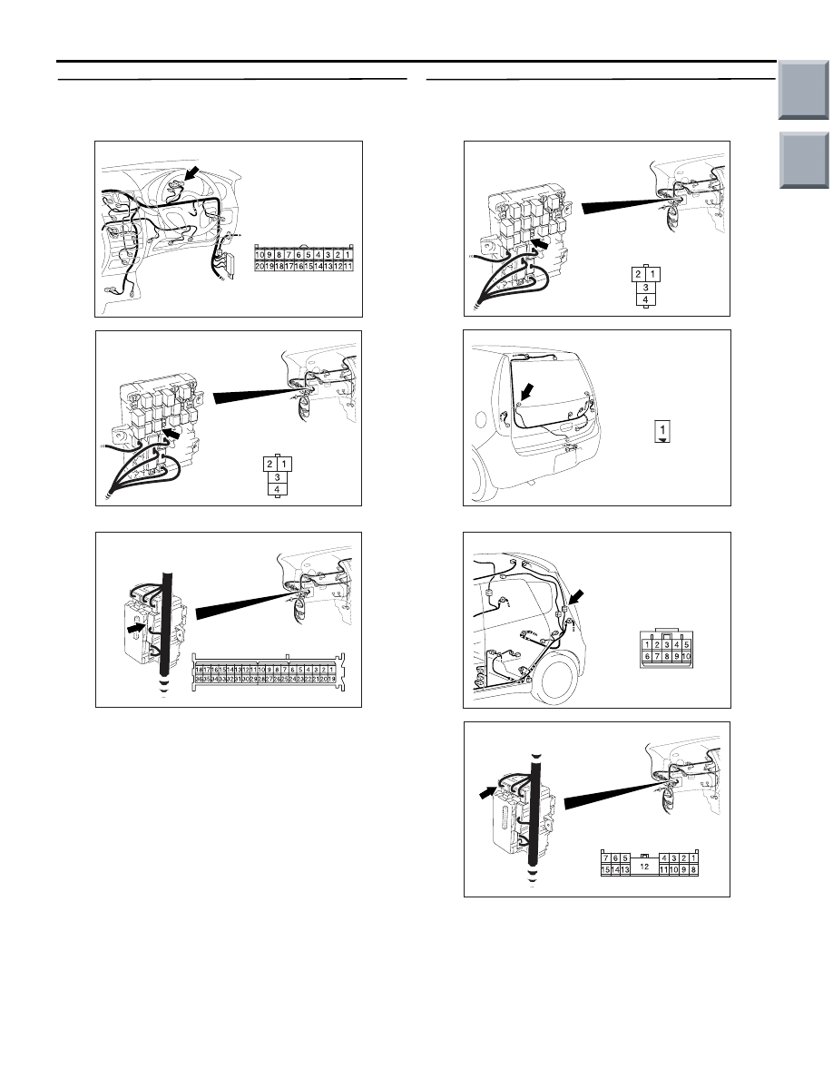
Step 10. Check the wiring harness between B-125 
rear window defogger relay connector No.2 and 
B-15 combination meter connector No.13.

AC401055

AE

Connector: B-15

B-15 (B)

Harness side

AC313824AK

Junction block side

Junction block (Front view)

Connector: B-125

NOTE: 

AC313826 AF

Connector: B-131

Junction Block (Rear view)

Harness side

Prior to the wiring harness inspection, check junction 
block connector B-131, and repair if necessary.

• Check the rear window defogger power supply 

line for open circuit.

Q: Is the check result normal?

YES : 

Go to Step 11.

NO : 

Repair the wiring harness.

Step 11. Check the wiring harness between B-125 
rear window defogger relay connector No.4 and 
E-13 rear window defogger connector No.1.

AC313824AK

Junction block side

Junction block (Front view)

Connector: B-125

AC401046

Connector: E-13

AF

Harness side

E-13 (B)

NOTE: 

AC401059

Connector: C-12

AC

AC313826

Harness side

AH

Connector: B-128

Junction block (Rear view)

Prior to the wiring harness inspection, check junction 
block connector B-128 and intermediate connector 
C-12, and repair if necessary.

• Check the rear window defogger relay line for 

open or short circuit.

Main

Index

Group

TOC

TROUBLESHOOTING

HEATER, AIR CONDITIONER AND VENTILATION

55A-37

Q: Is the check result normal?

YES : 

The trouble can be an intermittent 

malfunction (Refer to GROUP 00, How to 
Cope with Intermittent Malfunction 

P.00-13

).

NO : 

Repair the wiring harness.

Step 12. Connector check: E-02 rear window 
defogger connector

AC401046

Connector: E-02

AG

Harness side

E-02 (B)

Q: Is the check result normal?

YES : 

Go to Step 13.

NO : 

Repair the connector.

Step 13. Resistance measurement at E-02 rear 
window defogger connector.

AC401046

Connector: E-02

AG

Harness side

E-02 (B)

(1) Disconnect the connector, and measure at the 

wiring harness side.

AC400966

Connector E-02 
(Harness side)

AJ

(2) Continuity between terminal 1 and body earth.

OK: 2

 or less

Q: Is the check result normal?

YES : 

 Go to Step 15.

NO : 

 Go to Step 14.

Step 14. Check the wiring harness between E-02 
rear window defogger connector terminal No.1 
and earth.

AC401046

Connector: E-02

AG

Harness side

E-02 (B)

• Check the rear window defogger earth line for 

open or short circuit.

Q: Is the check result normal?

YES : 

The trouble can be an intermittent 

malfunction (Refer to GROUP 00, How to 
Cope with Intermittent Malfunction 

P.00-13

).

NO : 

Repair or replace the wiring harness.

Step 15. Check the rear window defogger.
Refer to GROUP 54A, Rear Window rear window 
defogger Inspection 

P.54A-122

.

Q: Does the rear window defogger work normally? 

YES : 

The trouble can be an intermittent 

malfunction (Refer to GROUP 00, How to 
Cope with Intermittent Malfunction 

P.00-13

).

NO : 

Repair the rear window defogger.

Main

Index

Group

TOC

TROUBLESHOOTING

HEATER, AIR CONDITIONER AND VENTILATION

55A-38

Inspection Procedure 9: The A/C indicator flashes

A/C PRESSURE
SENSOR

Wire colour code
B : Black     LG : Light green     G : Green     L : Blue     W : White     Y : Yellow     SB : Sky blue
BR : Brown     O : Orange     GR : Gray     R : Red     P : Pink     V : Violet

COMBINATION
METER

SENSOR CIRCUIT

METER AND A/C-ECU

A/C Pressure Circuit

CIRCUIT OPERATION

If the A/C pressure sensor detects the abnormal 
refrigerant pressure, the A/C indicator flashes. The 
inadequate refrigerant quantity or the malfunction of 
the A/C compressor system is suspected.

TROUBLESHOOTING HINTS

• Inadequate refrigerant level 

• Malfunction of the drive belt

• Malfunction of the A/C pressure sensor

• Damaged the wiring harness or connectors

• Malfunction of the combination meter (meter and 

A/C-ECU)

DIAGNOSIS PROCEDURE

Step 1. M.U.T.-III diagnosis code
Check that the diagnosis code related to the air con-
ditioner is not set.

Q: Is the check result normal?

YES : 

Go to Step 2.

NO : 

Carry out the diagnosis code procedures. 
Refer to 

P.55A-5

.

Step 2. Connector check: A-02 A/C pressure 
sensor connector

AC313797

Connector: A-02

Harness side

AF

A-02 (B)

Q:  Is the check result normal?

YES : 

Go to Step 3.

NO : 

Repair the connector.

Step 3. Inspection of A/C pressure sensor
 Refer to 

P.55A-51

.

Q:  Is the check result normal?

YES : 

Go to Step 4.

NO : 

Replace the A/C pressure sensor.

Main

Index

Group

TOC

TROUBLESHOOTING

HEATER, AIR CONDITIONER AND VENTILATION

55A-39

Step 4. Connector check: B-14 and B-15 
combination meter connector

AC401056

AI

Connectors: B-14, B-15

Harness side

B-15 (B)

B-15

B-14 (B)

Harness side

B-14

Q:  Is the check result normal?

YES : 

Go to Step 5.

NO : 

Repair the connector.

Step 5. Check the wiring harness between B-14, 
B-15 combination meter connector (terminals 8, 
34 and 30) and A-02 A/C pressure sensor 
connector (terminals 2, 1 and 3).

AC313797

Connector: A-02

Harness side

AF

A-02 (B)

AC401056

AI

Connectors: B-14, B-15

Harness side

B-15 (B)

B-15

B-14 (B)

Harness side

B-14

NOTE: 

AC401053

AD

Connector: B-41

Prior to the wiring harness inspection, check interme-
diate connector B-41, and repair if necessary.

• Check the input line for open circuit.

Main

Index

Group

TOC


Content   ..  530  531  532  533   ..