Mitsubishi Colt Ralliart. Manual - part 529


  Index      Mitsubishi     Mitsubishi Colt Ralliart - service repair manual


Search            


Content   ..  527  528  529  530   ..


Mitsubishi Colt Ralliart. Manual - part 529


TROUBLESHOOTING

HEATER, AIR CONDITIONER AND VENTILATION

55A-24

Inspection Procedure 6: The inside/outside air changeover is impossible

IGNITION
SWITCH (IG2)

OUTSIDE/INSIDE AIR
SELECTION DAMPER
CONTROL MOTOR

OUTSIDE/INSIDE
AIR SELECTION
DAMPER CONTROL MOTOR

COMBINATION
METER

METER AND A/C-ECU

Wire colour code
B : Black     LG : Light green     G : Green     L : Blue     W : White     Y : Yellow     SB : Sky blue
BR : Brown     O : Orange     GR : Gray     R : Red     P : Pink     V : Violet

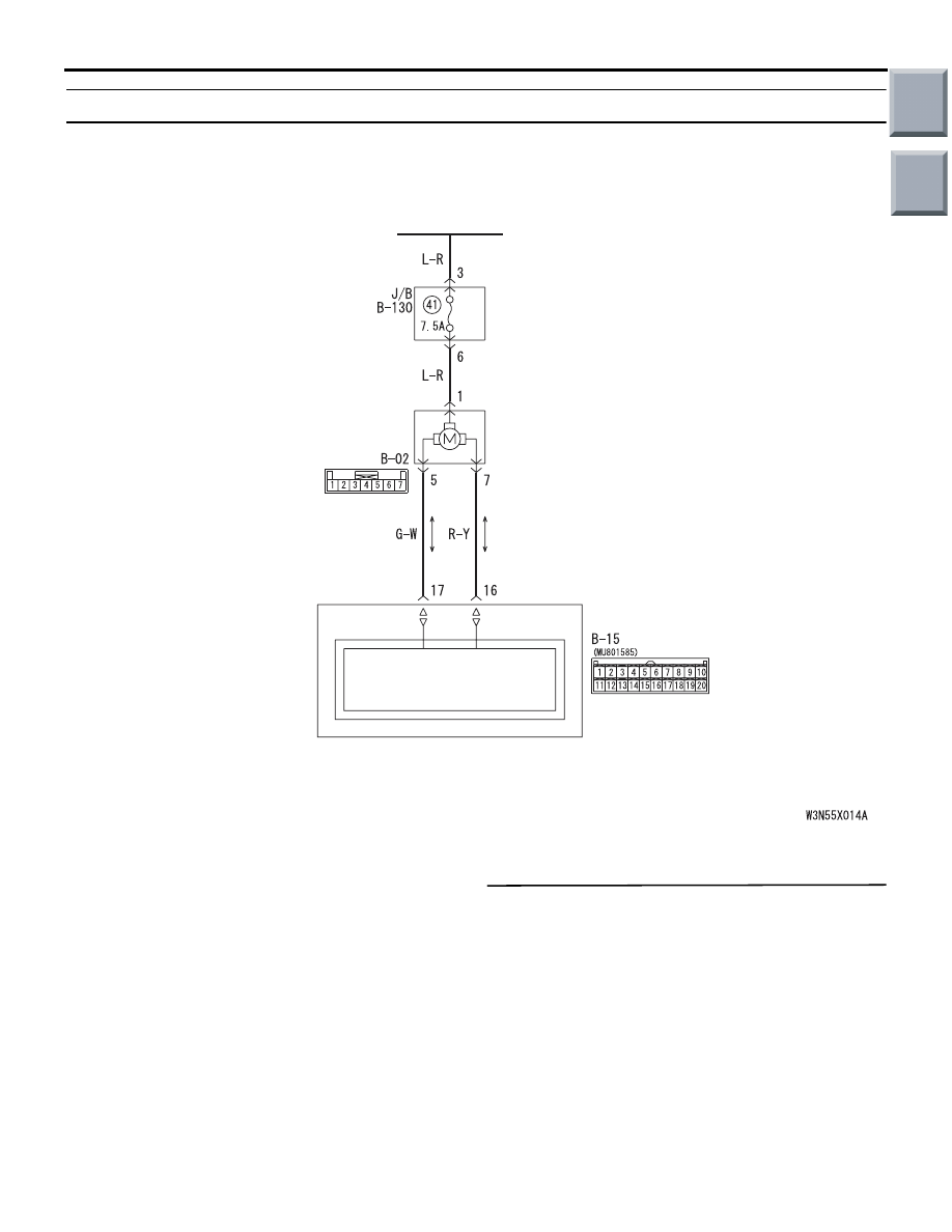
Outside/Inside Air Selection Damper Control Motor Circuit

COMMENTS ON TROUBLE SYMPTOM

When inside air cannot be changed to outside air 
vice versa even if its changeover switch is on, the 
outside/inside air selection damper control motor 
system may be defective.

POSSIBLE CAUSES

• Malfunction of the outside/inside air selection 

damper control motor

• Damaged the wiring harness or connectors

• Malfunction of the combination meter (meter and 

A/C-ECU)

DIAGNOSIS PROCEDURE

Step 1. M.U.T.-III diagnosis code
Check whether the air conditioner sets a diagnosis 
code or not.

Q: Is the check result normal?

YES : 

Go to Step 2.

NO : 

Refer to diagnosis code chart 

P.55A-5

.

Main

Index

Group

TOC

TROUBLESHOOTING

HEATER, AIR CONDITIONER AND VENTILATION

55A-25

Step 2. Connector check: B-02 outside/inside air 
selection damper control motor connector

AC401053

AG

Harness side

Connector: B-02

Q: Is the check result normal?

YES : 

Go to Step 3.

NO : 

Repair the connector.

Step 3. Voltage measurement at B-02 
outside/inside air selection damper control motor 
connector.

AC401053

AG

Harness side

Connector: B-02

(1) Disconnect the connector, and measure at the 

wiring harness side.

(2) Turn the ignition switch to the ON position.

AC310507EX

Connector B-02 
(Harness side)

(3) Measure the voltage between terminal 1 and 

body earth.

OK: System voltage

Q: Is the check result normal?

YES : . 

Go to Step 5.

NO : . 

Go to Step 4.

Step 4. Check the wiring harness between B-02 
outside/inside air selection damper control motor 
connector terminal No.1 and the ignition switch 
(IG2). 

AC401053

AG

Harness side

Connector: B-02

NOTE: 

AC313826

Harness side

AE

Connector: B-130

Junction block (Rear view)

Prior to the wiring harness inspection, check junction 
block connectors B-130, and repair if necessary.

• Check the motor power supply line for open cir-

cuit.

Q: Is the check result normal?

YES : 

The trouble can be an intermittent 

malfunction (Refer to GROUP 00, How to 
Cope with Intermittent Malfunction 

P.00-13

).

NO : 

Repair the wiring harness.

Step 5. Check the outside/inside air selection 
damper control motor
Refer to 

P.55A-61

.

Q: Is the check result normal?

YES : 

Go to Step 6.

NO : 

Replace the outside/inside air selection 
damper control motor.

Main

Index

Group

TOC

TROUBLESHOOTING

HEATER, AIR CONDITIONER AND VENTILATION

55A-26

Step 6. Connector check: B-15 combination 
meter connector

AC401055

AE

Connector: B-15

B-15 (B)

Harness side

Q: Is the check result normal?

YES : 

Go to Step 7.

NO : 

Repair the connector.

Step 7. Check the wiring harness between B-15 
combination meter connector (terminals 17 and 
16) and B-02 outside/inside air selection damper 
control motor connector (terminals 5 and 7).

AC401053

AG

Harness side

Connector: B-02

AC401055

AE

Connector: B-15

B-15 (B)

Harness side

• Check the motor activating lines for open or short 

circuit.

Q: Is the check result normal?

YES : 

Replace the combination meter (meter and 

A/C-ECU).

NO : 

Repair the wiring harness.

Main

Index

Group

TOC

TROUBLESHOOTING

HEATER, AIR CONDITIONER AND VENTILATION

55A-27

Inspection Procedure 7: The A/C compressor does not work

Wire colour code
B : Black     LG : Light green     G : Green     L : Blue     W : White     Y : Yellow     SB : Sky blue
BR : Brown     O : Orange     GR : Gray     R : Red     P : Pink     V : Violet

FUSIBLE
LINK

A/C
COMPRESSOR
RELAY

A/C
COMPRESSOR

A/C
REFRIGERANT
TEMPRATURE
SWITCH

ENGINE-CVT-
ECU

MAGNETIC
CLUTCH

6

A/C Compressor Circuit

COMMENTS ON TROUBLE SYMPTOM

When the A/C compressor does not work, the A/C 
compressor circuit system or the CAN bus line may 
be defective.

POSSIBLE CAUSES

• Malfunction of A/C compressor

• Malfunction of A/C compressor relay

• Malfunction of A/C pressure sensor

• Damaged harness wires and connectors

• Malfunction of engine-CVT-ECU

• Malfunction of the combination meter (meter and 

A/C-ECU)

Main

Index

Group

TOC


Content   ..  527  528  529  530   ..