Mitsubishi Colt Ralliart. Manual - part 527


  Index      Mitsubishi     Mitsubishi Colt Ralliart - service repair manual


Search            


Content   ..  525  526  527  528   ..


Mitsubishi Colt Ralliart. Manual - part 527


TROUBLESHOOTING

HEATER, AIR CONDITIONER AND VENTILATION

55A-16

DIAGNOSIS PROCEDURE

Step 1. Check that the blower motor operates 
when the blower switch is moved to the "4 (HI) " 
position.
(1) Turn the ignition switch to the "ON" position.
(2) Turn the blower switch to the "4 (HI) " position.

Q: Does the blower motor operate when the blower 

switch is moved to the "4 (HI) " position?
YES : 

Refer to Inspection procedure 5 "The blower 

air volume cannot be changed 

P.55A-21

."

NO : 

Go to Step 2.

Step 2. Connector check: B-10 blower motor 
connector

AC401055

Connector: B-10

AL

Harness side

Q: Is the check result normal?

YES : 

Go to Step 3.

NO : 

Repair the connector.

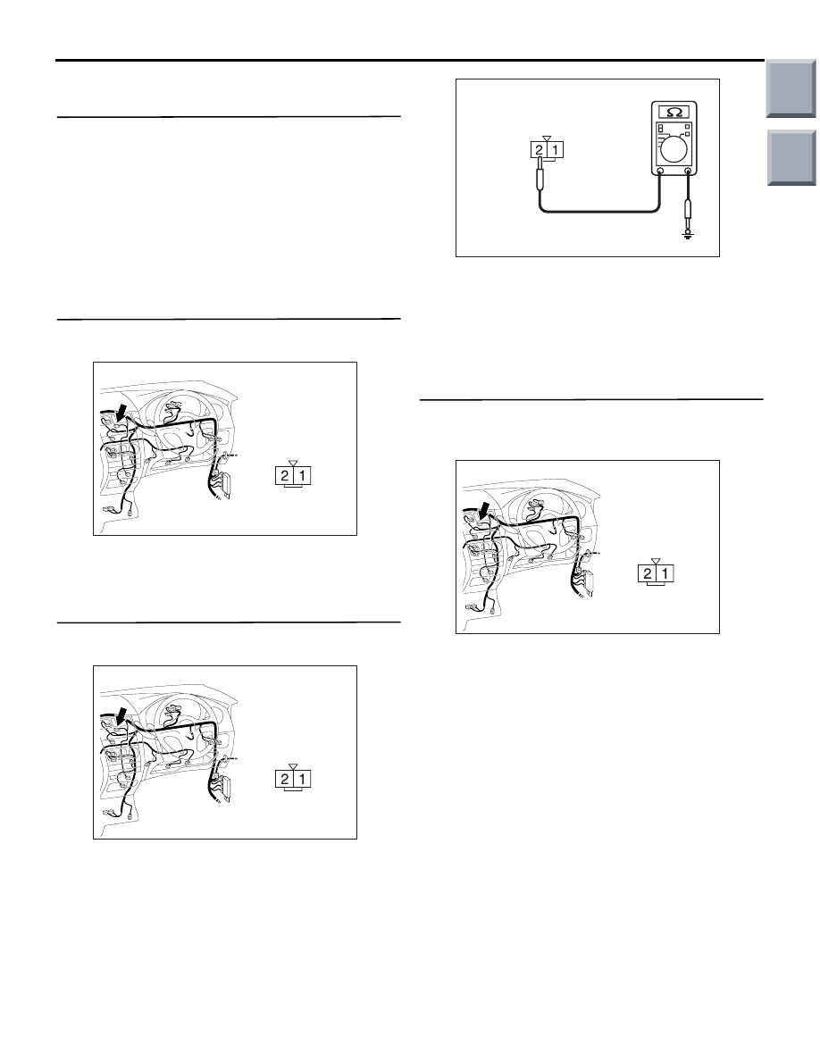
Step 3. Resistance measurement at the B-10 
blower motor connector.

AC401055

Connector: B-10

AL

Harness side

(1) Disconnect the connector, and measure at the 

wiring harness side.

AC310506DU

Connector B-10
(Harness side)

(2) Measure the resistance between terminal 2 and 

body earth.

OK: 2 ohms or less

Q: Is the check result normal?

YES : 

 Go to Step 5.

NO : 

Go to Step 4.

Step 4. Check the wiring harness between B-10 
blower motor connector terminal No.2 and body 
earth.

AC401055

Connector: B-10

AL

Harness side

• Check the blower motor earth line for open cir-

cuit.

Q: Is the check result normal?

YES : 

The trouble can be an intermittent 

malfunction (Refer to GROUP 00, How to 
Cope with Intermittent Malfunction 

P.00-13

).

NO : 

Repair the wiring harness.

Main

Index

Group

TOC

TROUBLESHOOTING

HEATER, AIR CONDITIONER AND VENTILATION

55A-17

Step 5. Voltage measurement at B-10 blower 
motor connector.

AC401055

Connector: B-10

AL

Harness side

(1) Disconnect the connector, and measure at the 

wiring harness side.

(2) Turn the ignition switch to the "ON" position.
(3) Turn the blower switch to the "4 (HI) " position.

AC310507 EU

Connector B-10
(Harness side)

(4) Measure the voltage between terminal 1 and 

body earth.

OK: System voltage

Q: Is the check result normal?

YES : 

Go to Step 18.

NO : 

Go to Step 6.

Step 6. Connector check: B-116 blower relay 
connector

AC313824

Connector: B-116

AD

Junction block side

Junction block (Front view)

Q: Is the check result normal?

YES : 

Go to Step 7.

NO : 

Repair the connector. 

Step 7. Check the blower relay continuity.
 Refer to 

P.55A-52

.

Q: Is the blower relay continuity in good condition?

YES : 

Go to Step 8.

NO : 

Replace the blower relay.

Step 8. Voltage measurement at B-116 blower 
relay connector.

AC313824

Connector: B-116

AD

Junction block side

Junction block (Front view)

(1) Remove the relay, and measure at the junction 

block side.

(2) Turn the ignition switch to the "ON" position.

AC310507EV

Connector B-116
(Junction block side)

(3) Measure the voltage between terminal 1 and 

earth.

OK: System voltage

Q: Is the check result normal?

YES : 

 Go to Step 10.

NO : 

Go to Step 9.

Main

Index

Group

TOC

TROUBLESHOOTING

HEATER, AIR CONDITIONER AND VENTILATION

55A-18

Step 9. Check the wiring harness between B-116 
blower relay connector terminal No.1 and the 
ignition switch (IG2).

AC313824

Connector: B-116

AD

Junction block side

Junction block (Front view)

NOTE: 

AC313826

Harness side

AE

Connector: B-130

Junction block (Rear view)

Prior to the wiring harness inspection, check junction 
block connector B-130, and repair if necessary.

• Check the blower relay power supply line for 

open circuit.

Q: Is the check result normal?

YES : 

The trouble can be an intermittent 

malfunction (Refer to GROUP 00, How to 
Cope with Intermittent Malfunction 

P.00-13

).

NO : 

Repair the wiring harness.

Step 10. Resistance measurement at B-116 
blower relay connector.

AC313824

Connector: B-116

AD

Junction block side

Junction block (Front view)

(1) Remove the relay, and measure at the junction 

block side. 

AC310506 DV

Connector B-116 
(Junction block side)

(2) Measure the resistance Continuity between 

terminal 2 and body earth.

OK: 2 ohms or less

Q: Is the check result normal?

YES : 

 Go to Step 12.

NO : 

Go to Step 11.

Step 11. Check the wiring harness between B-116 
blower relay connector terminal No.2 and earth.

AC313824

Connector: B-116

AD

Junction block side

Junction block (Front view)

NOTE: 

AC313826 AF

Connector: B-131

Junction Block (Rear view)

Harness side

Prior to the wiring harness inspection, check junction 
block connectors B-131, and repair if necessary.

• Check the blower relay earth wires for open cir-

cuit.

Q: Is the check result normal?

YES : 

The trouble can be an intermittent 

malfunction (Refer to GROUP 00, How to 
Cope with Intermittent Malfunction 

P.00-13

).

NO : 

Repair the wiring harness.

Main

Index

Group

TOC

TROUBLESHOOTING

HEATER, AIR CONDITIONER AND VENTILATION

55A-19

Step 12. Voltage measurement at B-116 blower 
relay connector.

AC313824

Connector: B-116

AD

Junction block side

Junction block (Front view)

(1) Remove the relay, and measure at the junction 

block side.

AC310507 EW

Connector B-116
(Junction block side)

(2) Measure the voltage between terminal 3 and 

body earth.

OK: System voltage

Q: Is the check result normal?

YES : 

 Go to Step 14.

NO : 

Go to Step 13.   

Step 13. Check the wiring harness between B-116 
blower relay connector terminal No.3 and fusible 
link (6).

AC313825 AE

Connectors: B-108, B-116

Junction Block (Front view)

B-116

B-108 (B)

Harness side

B-108

Junction block side

B-116

NOTE: Prior to the wiring harness inspection, check 
junction block connector B-108, and repair if neces-
sary.

• Check the blower relay power supply line for 

open circuit.

Q: Is the check result normal?

YES : 

The trouble can be an intermittent 

malfunction (Refer to GROUP 00, How to 
Cope with Intermittent Malfunction 

P.00-13

).

NO : 

Repair the wiring harness.

Step 14. Connector check: B-31 blower switch 
connector

AC401055

Connector: B-31

AM

Harness side

B-31 (B)

Q: Is the check result normal?

YES : 

Go to Step 15.

NO : 

Repair the connector.

Main

Index

Group

TOC


Content   ..  525  526  527  528   ..