Mitsubishi Colt Ralliart. Manual - part 430
INPUT SIGNAL PROCEDURES
SMART WIRING SYSTEM (SWS) USING SWS MONITOR
54C-228
Step 4. Check the wiring harness between D-08
front door lock actuator (RH) connector terminal
No.3 to body earth D-08
NOTE:
Prior to the wiring harness inspection, check interme-
diate connector B-21, and repair if necessary.
• Check the earth wires for open circuit.
Q: Is the check result normal?
YES :
The trouble can be an intermittent
malfunction (Refer to GROUP 00
− How to
use Troubleshooting/inspection Service
Points
− How to Cope with Intermittent
).
NO :
Repair the wiring harness.
Step 5. Connector check: B-132 ETACS-ECU
connector
Q: Is the check result normal?
YES :
Go to Step 6.
NO :
Repair the defective connector.
Step 6. Check the wiring harness from D-08 front
door lock actuator (RH) connector terminal No.1
and 2 to B-132 ETACS-ECU connector terminal
No.41 and 36.
NOTE:
Prior to the wiring harness inspection, check interme-
diate connector B-21, and repair if necessary.
• Check the input line for open circuit.
Q: Is the check result normal?
YES :
Go to Step 7.
NO :
Repair the wiring harness.
AC313837
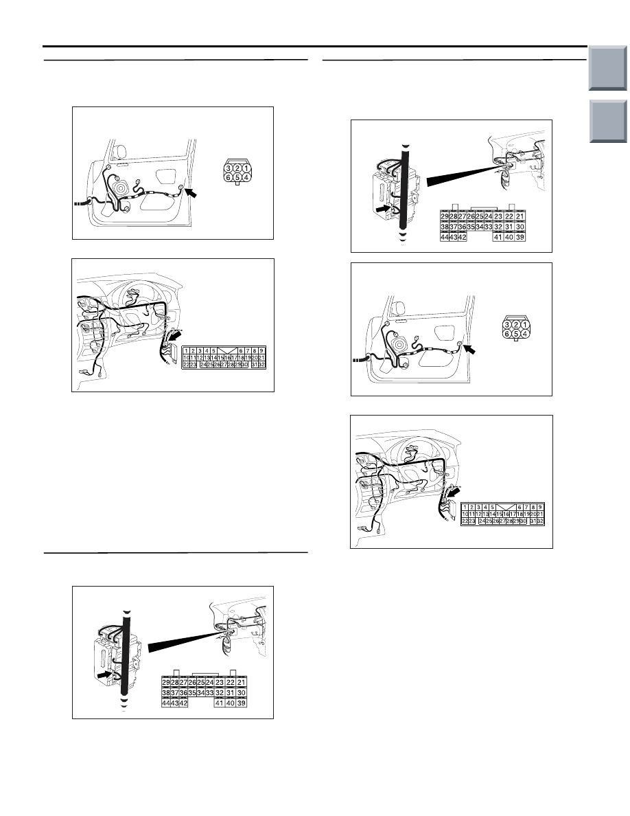
Connector: D-08
D-08 (B)
AB
Harness side
AC401055
Connector: B-21
AB
AC313826 AD
Connector: B-132
Junction block (Rear view)
Harness side
AC313826 AD
Connector: B-132
Junction block (Rear view)
Harness side
AC313837
Connector: D-08
D-08 (B)
AB
Harness side
AC401055
Connector: B-21
AB
Main
Index
Group
TOC