Mitsubishi Colt Ralliart. Manual - part 410


  Index      Mitsubishi     Mitsubishi Colt Ralliart - service repair manual


Search            


Content   ..  408  409  410  411   ..


Mitsubishi Colt Ralliart. Manual - part 410


SYMPTOM PROCEDURES

SMART WIRING SYSTEM (SWS) USING SWS MONITOR

54C-148

DIAGNOSTIC PROCEDURE

Step 1. Connector check: A-12 front combination 
lamp (HEAD: LH) connector or A-25 front 
combination lamp (HEAD: RH) connector

Q: Is the check result normal?

YES (Either of LH side and RH side does not 
illuminate) : 

Go to Step 2.

YES (Low-beam of LH side or RH side does not 
illuminate) : 

Go to Step 5.

YES (High-beam of LH side or RH side does not 
illuminate) : 

Go to Step 9.

NO (the connectors are not in good condition) : 

Repair the defective connector.

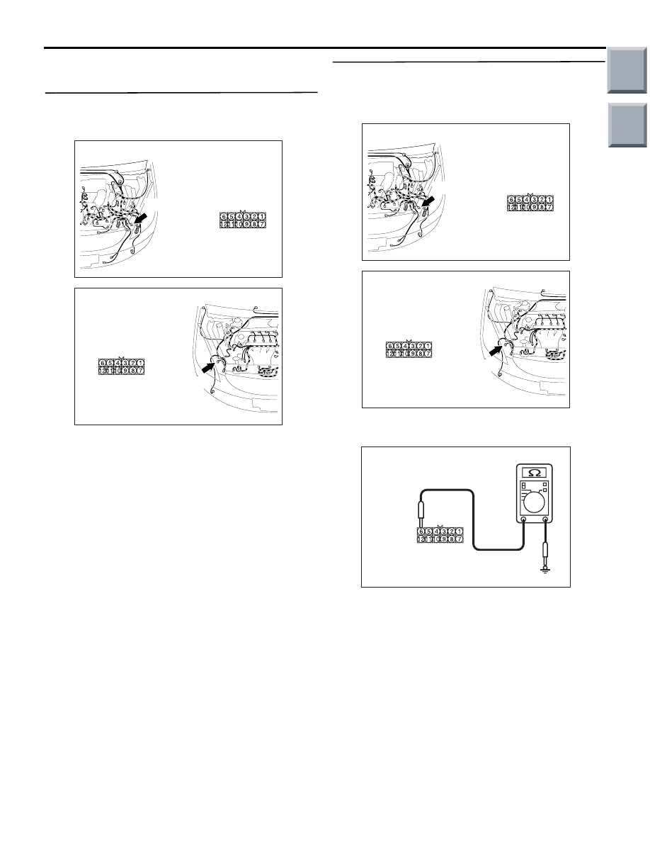
Step 2. Resistance measurement at the A-12 front 
combination lamp (HEAD: LH) connector or the 
A-25 front combination lamp (HEAD: RH) 
connector.

(1) Disconnect the connector, and measure at the 

wiring harness side.

(2) Check the resistance between the lamp 

connector and body earth.

• Resistance between A-12 front combination 

lamp (HEAD: LH) connector terminal No.6 
and body earth

• Resistance between A-25 front combination 

lamp (HEAD: RH) connector terminal No.6 
and body earth

OK: Continuity exists (2 

 or less)

Q: Is the check result normal?

YES : 

Go to Step 4.

NO : 

Go to Step 3.

AC509191

Connector: A-12

Harness side

AB

A-12 (B)

AC509176

Connector: A-25

Harness side

AC

A-25(B)

AC509191

Connector: A-12

Harness side

AB

A-12 (B)

AC509176

Connector: A-25

Harness side

AC

A-25(B)

AC313972 DJ

Connectors: A-12, A-25

(Harness side)

Main

Index

Group

TOC

SYMPTOM PROCEDURES

SMART WIRING SYSTEM (SWS) USING SWS MONITOR

54C-149

Step 3. Check the wiring harness from A-12 front 
combination lamp (HEAD: LH) connector 
terminal No.6 or A-25 front combination lamp 
(HEAD: RH) connector terminal No.6 to body 
earth.

• Check the earth wires for open circuit.

Q: Is the check result normal?

YES : 

The trouble can be an intermittent 

malfunction (Refer to GROUP 00 

− How to 

use Troubleshooting/inspection Service 
Points 

− How to Cope with Intermittent 

Malfunction 

P.00-13

).

NO : 

Repair the wiring harness.

Step 4. Retest the system.
(1) Replace the socket of the defective headlamp.
(2) Check that the headlamps illuminate normally.

Q: Is the check result normal?

YES : 

The trouble can be an intermittent 

malfunction (Refer to GROUP 00 

− How to 

use Troubleshooting/inspection Service 
Points 

− How to Cope with Intermittent 

Malfunction 

P.00-13

).

NO : 

Replace the front combination lamp.

Step 5. Check the bulb(s) of the headlamps.
Check the bulb(s) of the defective lamp.

Q: Is the check result normal?

YES : 

Go to Step 6.

NO : 

Replace the bulb(s) of the defective lamp.

Step 6. Connector check: B-123 headlamp relay 
(LO) connector

Q: Is the check result normal?

YES : 

Go to Step 7.

NO : 

Repair the defective connector.

AC509191

Connector: A-12

Harness side

AB

A-12 (B)

AC509176

Connector: A-25

Harness side

AC

A-25(B)

AC313870 AD

Connector: B-123

Junction Block (Front view)

Harness side

Main

Index

Group

TOC

SYMPTOM PROCEDURES

SMART WIRING SYSTEM (SWS) USING SWS MONITOR

54C-150

Step 7. Check the wiring harness from A-12 front 
combination lamp (HEAD: LH) connector 
terminal No.4 or A-25 front combination lamp 
(HEAD: RH) connector terminal No.4 to B-123 
headlamp relay (LO) connector terminal No.4.

NOTE: 

Prior to the wiring harness inspection, check junction 
block connector B-112, and repair if necessary.

• Check the output lines for open circuit.

Q: Is the check result normal?

YES : 

Go to Step 8.

NO : 

Repair the wiring harness.

Step 8. Retest the system.
(1) Replace the socket of the defective headlamp.
(2) Check that the headlamps illuminate normally.

Q: Is the check result normal?

YES : 

The trouble can be an intermittent 

malfunction (Refer to GROUP 00 

− How to 

use Troubleshooting/inspection Service 
Points 

− How to Cope with Intermittent 

Malfunction 

P.00-13

).

NO : 

Replace the front combination lamp.

Step 9. Check the bulb(s) of the headlamps.
Check the bulb(s) of the defective lamp.

Q: Is the check result normal?

YES : 

Go to Step 10.

NO : 

Replace the bulb(s) of the defective lamp.

Step 10. Connector check: B-122 headlamp relay 
(HI) connector

Q: Is the check result normal?

YES : 

Go to Step 11.

NO : 

Repair the defective connector.

AC509191

Connector: A-12

Harness side

AB

A-12 (B)

AC509176

Connector: A-25

Harness side

AC

A-25(B)

AC313870 AD

Connector: B-123

Junction Block (Front view)

Harness side

AC313870

Connector: B-112

BE

Junction block (Front view)

Harness side

AC313870AE

Connector: B-122

Junction Block (Front view)

Harness side

Main

Index

Group

TOC

SYMPTOM PROCEDURES

SMART WIRING SYSTEM (SWS) USING SWS MONITOR

54C-151

Step 11. Check the wiring harness from A-12 
front combination lamp (HEAD: LH) connector 
terminal No.11 or A-25 front combination lamp 
(HEAD: RH) connector terminal No.11 to B-122 
headlamp relay (HI) connector terminal No.4.

NOTE: 

Prior to the wiring harness inspection, check junction 
block connector B-112, and repair if necessary.

• Check the output lines for open circuit.

Q: Is the check result normal?

YES : 

Go to Step 12.

NO : 

Repair the wiring harness.

Step 12. Retest the system.
(1) Replace the socket of the defective headlamp.
(2) Check that the headlamps illuminate normally.

Q: Is the check result normal?

YES : 

The trouble can be an intermittent 

malfunction (Refer to GROUP 00 

− How to 

use Troubleshooting/inspection Service 
Points 

− How to Cope with Intermittent 

Malfunction 

P.00-13

).

NO : 

Replace the front combination lamp.

AC509191

Connector: A-12

Harness side

AB

A-12 (B)

AC509176

Connector: A-25

Harness side

AC

A-25(B)

AC313870AE

Connector: B-122

Junction Block (Front view)

Harness side

AC313870

Connector: B-112

BE

Junction block (Front view)

Harness side

Main

Index

Group

TOC


Content   ..  408  409  410  411   ..