Mitsubishi Colt Ralliart. Manual - part 409


  Index      Mitsubishi     Mitsubishi Colt Ralliart - service repair manual


Search            


Content   ..  407  408  409  410   ..


Mitsubishi Colt Ralliart. Manual - part 409


SYMPTOM PROCEDURES

SMART WIRING SYSTEM (SWS) USING SWS MONITOR

54C-144

Step 2. Function diagnosis by using the SWS 
monitor
Check the SWS communication signal, which are 
related to the high-beam headlamps.

<Selected item> LIGHTING - HEADLAMP HI

• Ignition switch: ON

• Lighting switch: HEAD

• Dimmer switch: from OFF to ON, and then to 

OFF again

OK: Normal conditions are displayed for all 
the items

Q: Are the check results normal?

Normal conditions are displayed for all the items. : 

Go to Step 3.

Normal condition is not displayed for item Nos.00, 
02 or 03. : 

Refer to inspection procedure N-4 "The 

column switch (lighting and turn-signal lamp 
switch) signal is not received 

P.54C-208

."

Normal condition is not displayed for item No.30. : 

Refer to inspection procedure N-2 "The 
ignition switch (IG1) signal is not received 

P.54C-203

."

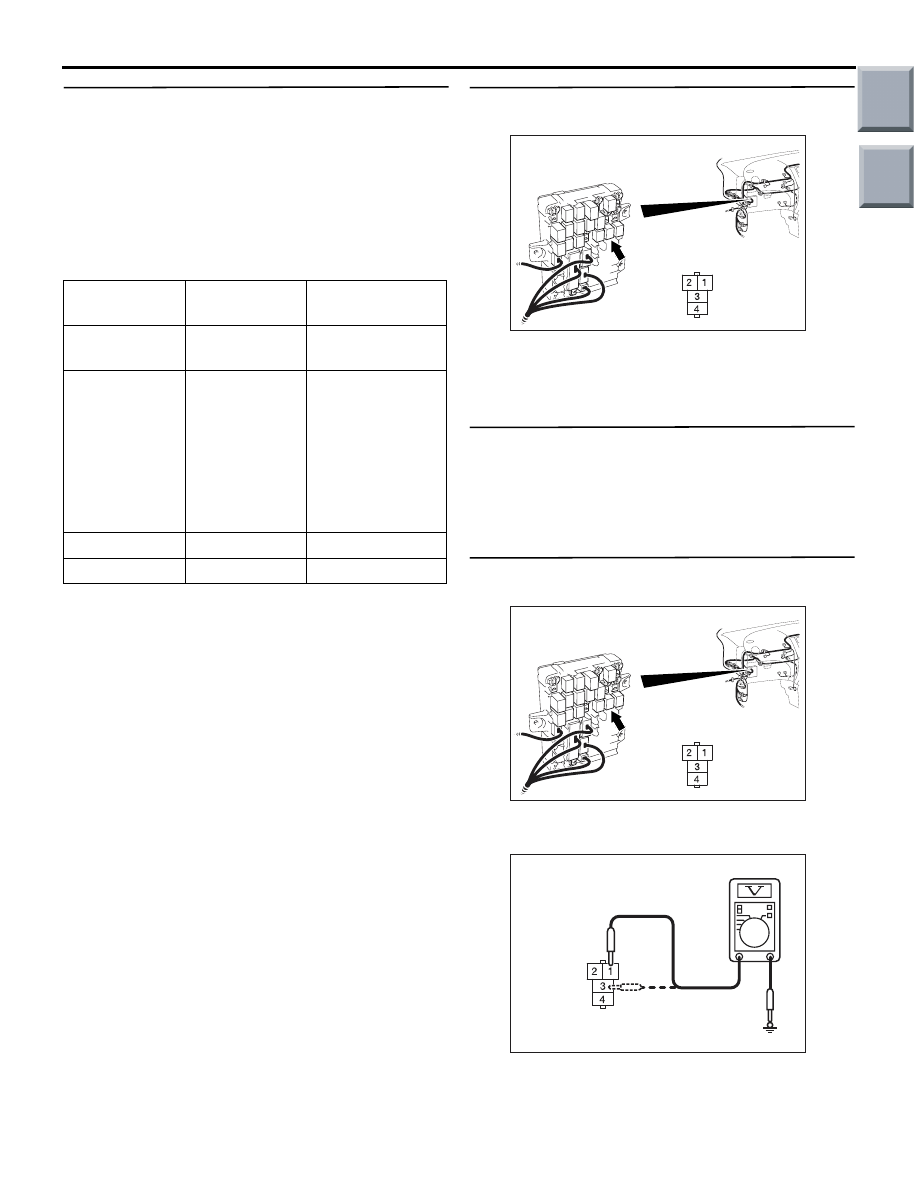
Step 3. Connector check: B-122 headlamp relay 
(HI) connector

Q: Is the check result normal?

YES : 

Go to Step 4.

NO : 

Repair the defective connector.

Step 4. Check the headlamp relay (HI).
Refer to GROUP 54A 

 Headlamp 

P.54A-74

.

Q: Is the check result normal?

YES : 

Go to Step 5.

NO : 

Replace the headlamp relay (HI).

Step 5. Voltage measurement at B-122 headlamp 
relay (HI) connector.

(1) Remove the headlamp relay (HI), and measure at 

the junction block side.

(2) Voltage between B-122 headlamp relay (HI) 

connector terminal Nos.1, 3 and body earth

OK: System voltage

Item No.

Item name

Normal 
condition

Item 00

HEADLAMP 
SW

ON

Item 02

DIMMER SW

from OFF to ON, 
and then to OFF 
again ("ON" 
should be 
displayed when 
the dimmer 
switch is 
operated)

Item 03

PASSING SW OFF

Item 30

IG SW(IG1)

ON

AC313870AE

Connector: B-122

Junction Block (Front view)

Harness side

AC313870AE

Connector: B-122

Junction Block (Front view)

Harness side

AC313972AU

Connector B-122 
(Junction block side)

Main

Index

Group

TOC

SYMPTOM PROCEDURES

SMART WIRING SYSTEM (SWS) USING SWS MONITOR

54C-145

Q: Is the check result normal?

YES : 

Go to Step 7.

NO : 

Go to Step 6.

Step 6. Check the wiring harness between B-122 
headlamp relay (HI) connector terminal Nos.1, 3 
and the fusible link (1).

NOTE: 

Prior to the wiring harness inspection, check the 
junction block connector B-108, and repair if neces-
sary.

• Check the power supply line from the fusible link 

(1) for open circuit.

Q: Is the check result normal?

YES : 

The trouble can be an intermittent 

malfunction (Refer to GROUP 00 

− How to 

use Troubleshooting/inspection Service 
Points 

− How to Cope with Intermittent 

Malfunction 

P.00-13

).

NO : 

Repair the wiring harness.

Step 7. Connector check: B-134 ETACS-ECU 
connector

Q: Is the check result normal?

YES : 

Go to Step 8.

NO : 

Repair the defective connector.

Step 8. Retest the system.
Check that the low-beam headlamps illuminate nor-
mally.

Q: Is the check result normal?

YES : 

The trouble can be an intermittent 

malfunction (Refer to GROUP 00 

− How to 

use Troubleshooting/inspection Service 
Points 

− How to Cope with Intermittent 

Malfunction 

P.00-13

).

NO : 

Replace the ETACS-ECU.

AC313870AE

Connector: B-122

Junction Block (Front view)

Harness side

AC313870

Connector: B-108

BD

Junction block (Front view)

B-108(B)

Harness side

AC313872 AH

Connector: B-134

Harness side

Junction block (Rear view)

Main

Index

Group

TOC

SYMPTOM PROCEDURES

SMART WIRING SYSTEM (SWS) USING SWS MONITOR

54C-146

INSPECTION PROCEDURE J-4: The high-beam and low-beam headlamps do not illuminate when the 
passing switch is operated.

CAUTION

Whenever the ECU is replaced, ensure that the 
input and output signal circuits are normal.

COMMENTS ON TROUBLE SYMPTOM

If the low-beam and high-beam headlamps are nor-
mal, the passing switch input signal circuit or the 
ETACS-ECU may be defective.

POSSIBLE CAUSES

• Malfunction of the column switch

• Malfunction of the ETACS-ECU

• Damaged harness wires and connectors

DIAGNOSIS PROCEDURE

Step 1. Check the operation of the headlamps.
Check that the low-beam and high-beam headlamps 
illuminate normally.

Q: Is the check result normal?

YES : 

Go to Step 2.

NO : 

Repair the headlamps. Refer to trouble 
symptom chart 

P.54C-29

.

Step 2. SWS monitor data list.
Check the ETACS-ECU signals which are related to 
the headlamps.

<Selected item> COLUMN ECU

• Passing lamp switch: ON

OK: Normal condition is displayed.

Q: Is the check result normal?

YES : 

Go to Step 3.

NO : 

Refer to inspection procedure N-4 "The 
column switch (lighting and turn-signal lamp 
switch) signal is not received 

P.54C-208

."

Step 3. Retest the system.
When the passing switch is turned on, check if the 
headlamps illuminate normally.

Q: Is the check result normal?

YES : 

The trouble can be an intermittent 

malfunction (Refer to GROUP 00 

− How to 

use Troubleshooting/inspection Service 
Points 

− How to Cope with Intermittent 

Malfunction 

P.00-13

).

NO : 

Replace the ETACS-ECU.

Item No.

Item name

Normal 
condition

Item 03

PASSING SW

ON

Main

Index

Group

TOC

SYMPTOM PROCEDURES

SMART WIRING SYSTEM (SWS) USING SWS MONITOR

54C-147

 INSPECTION PROCEDURE J-5: The headlamp(s) do not illuminate.

CAUTION

Whenever the ECU is replaced, ensure that the 
input and output signal circuits are normal.

COMMENTS ON TROUBLE SYMPTOM

If any of the headlamps does not illuminate, the wir-
ing harness connector(s), the bulb or the fuse may 
be defective or burned out.

POSSIBLE CAUSES

• Malfunction of the headlamp bulbs

• Damaged harness wires and connectors

HEADLAMP
RELAY (HI)

HEADLAMP
RELAY (LO)

FRONT
COMBINATION
LAMP
(HEAD: LH)

FRONT
COMBINATION
LAMP 
(HEAD: RH)

Headlamps Circuit

Wire colour code
B : Black     LG : Light green     G : Green     L : Blue     W : White     Y : Yellow     SB : Sky blue
BR : Brown     O : Orange     GR : Grey     R : Red     P : Pink     V : Violet     PU : Purple

Main

Index

Group

TOC


Content   ..  407  408  409  410   ..