Mitsubishi Colt Ralliart. Manual - part 406


  Index      Mitsubishi     Mitsubishi Colt Ralliart - service repair manual


Search            


Content   ..  404  405  406  407   ..


Mitsubishi Colt Ralliart. Manual - part 406


SYMPTOM PROCEDURES

SMART WIRING SYSTEM (SWS) USING SWS MONITOR

54C-132

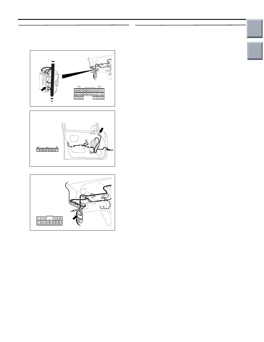
Step 9. Check the wiring harness between D-15 
door mirror assembly (LH) connector terminal 
No.7 to B-132 ETACS-ECU connector terminal 
No.40

NOTE: 

Prior to the wiring harness inspection, check interme-
diate connector B-42, and repair if necessary.

• Check the input and output signal line for open 

circuit.

Q: Is the check result normal?

YES : 

Go to Step 10.

NO : 

Repair the wiring harness.

Step 10. Retest the system
Check that the electric retractable remote controlled 
mirror works normally.

Q: Is the check result normal?

YES : 

The trouble can be an intermittent 

malfunction (Refer to GROUP 00 

− How to 

use Troubleshooting/inspection Service 
Points 

− How to Cope with Intermittent 

Malfunction 

P.00-13

).

NO : 

Replace the ETACS-ECU.

AC313872

Connector: B-132

AI

Harness side

Junction block (Rear view)

AC313886

Connector: D-15

Harness side

AC

AC401053

Connector: B-42

AB

Main

Index

Group

TOC

SYMPTOM PROCEDURES

SMART WIRING SYSTEM (SWS) USING SWS MONITOR

54C-133

IGNITION KEY CYLINDER 
ILLUMINATION LAMP

INSPECTION PROCEDURE I-1: The ignition key cylinder illumination lamp does not 
illuminate/extinguish normally.

CAUTION

Whenever the ECU is replaced, ensure that the 
input and output signal circuits are normal.

COMMENTS ON TROUBLE SYMPTOM

The ETACS-ECU operates this function in accord-
ance with the input signals below.

• Ignition switch (IG1)

• Key reminder switch

• Driver's door switch

If this function does not work normally, these input 
signal circuit(s), the ignition key cylinder illumination 
lamp or the ETACS-ECU may be defective.

POSSIBLE CAUSES

• Malfunction of the key reminder switch

• Malfunction of the driver's door switch

• Malfunction of the ignition key cylinder illumina-

tion lamp

• Malfunction of the ETACS-ECU

• Damaged harness wires and connectors

DIAGNOSIS PROCEDURE

Step 1. Check the operation of the interior lamp.
Check that the interior lamps illuminate and extin-
guish normally.

Q: Is the check result normal?

YES : 

Go to Step 2.

NO : 

Refer to inspection procedure M-1 "The 
interior lamps (room ramp, luggage 
compartment lamp) does not illuminate or 
extinguish normally 

P.54C-186

."

Ignition Key Cylinder Illumination Lamp Circuit

KEY REMINDER SWITCH

ETACS-ECU

Wire colour code
B : Black     LG : Light green     G : Green     L : Blue     W : White     Y : Yellow     SB : Sky blue
BR : Brown     O : Orange     GR : Gray     R : Red     P : Pink     V : Violet   

KEY CYLINDER
ILLUMINATION LAMP

FUSIBLE
LINK

1

Main

Index

Group

TOC

SYMPTOM PROCEDURES

SMART WIRING SYSTEM (SWS) USING SWS MONITOR

54C-134

Step 2. ECU check by using the SWS monitor.
Check that the power supply and earth lines to the 
ETACS-ECU and the SWS communication lines are 
normal.

• Ignition switch: OFF

ECU TO BE CHECKED

• ETACS ECU

OK: "OK" is displayed on the "ETACS ECU" 
menu.

Q: Is the check result normal?

YES : 

Go to Step 3.

NO : 

Refer to Inspection Procedure A-3 
"Communication with the ETACS-ECU is 
not possible 

P.54C-41

."

Step 3. SWS monitor data list
Check the SWS communication signal, which are 
related to the ignition key cylinder illumination lamp.

<Selected item> ETACS ECU

• Ignition switch: OFF

• Driver's door: open

OK: Normal conditions are displayed for all 
the items

Q: Are the check result normal?

Normal conditions are displayed for all the items.  : 

Go to Step 4.

Normal condition is not displayed for item No.30. : 

Refer to inspection procedure N-2 "The 
ignition switch (IG1) signal is not received 

P.54C-203

."

Normal condition is not displayed for item No.32. : 

Refer to inspection procedure N-3 "The 
driver's door switch signal is not received 

P.54C-205

."

Step 4. ETACS switch data by using the SWS 
monitor
Check the ETACS-ECU signals related to the ignition 
key cylinder illumination lamp. 

• Ignition switch: OFF (key inserted)

OK: Normal condition is displayed.

Q: Is the check result normal?

YES : 

Go to Step 5

NO : 

Refer to inspection procedure N-7 "The key 
reminder switch signal is not received 

P.54C-213

." 

Step 5. Connector check: B-140 key reminder 
switch connector.

Q: Is the check result normal?

YES : 

Go to Step 6.

NO : 

Repair the defective connector.

Step 6. Check the bulb of the ignition key 
cylinder illumination lamp.
Check the bulb of the ignition key cylinder illumina-
tion lamp.

Q: Is the check result normal?

YES : 

Go to Step 7.

NO : 

Replace the bulb of the ignition key cylinder 
illumination lamp.

Item No.

Item name

Normal 
condition

Item 30

IG SW(IG1)

OFF

Item 32

DR DOOR SW

ON

Item No.

Item name

Normal 
condition

Item 03

KEY REMIN SW

OFF

AC401044

Connector: B-140

AB

Harness side

B-140(B)

Main

Index

Group

TOC

SYMPTOM PROCEDURES

SMART WIRING SYSTEM (SWS) USING SWS MONITOR

54C-135

Step 7. Voltage measurement at B-140 key 
reminder switch connector

(1) Disconnect the connector, and measure at the 

wiring harness side.

(2) Resistance between B-140 key reminder switch 

connector terminal No.2 and body earth

OK: System voltage

Q: Is the check result normal?

YES : 

Go to Step 9.

NO : 

Go to Step 8.

Step 8. Check the wiring harness from B-140 key 
reminder switch connector terminal No.2 to 
fusible link (1)

NOTE: 

Prior to the wiring harness inspection, check interme-
diate connector B-22, and joint connector B-108, and 
junction block connector B-131 and repair if neces-
sary.

• Check the power supply line for open circuit.

Q: Is the check result normal?

YES : 

Go to Step 11.

NO : 

Repair the wiring harness.

AC401044

Connector: B-140

AB

Harness side

B-140(B)

AC313972

Connector B-140
 (Harness side)

AS

AC401044

Connector: B-140

AB

Harness side

B-140(B)

AC401055

Connector: B-22

AD

AC313870

Connector: B-108

BD

Junction block (Front view)

B-108(B)

Harness side

AC313872

Connector: B-131

BD

Harness side

Main

Index

Group

TOC


Content   ..  404  405  406  407   ..