Mitsubishi Colt Ralliart. Manual - part 393


  Index      Mitsubishi     Mitsubishi Colt Ralliart - service repair manual


Search            


Content   ..  391  392  393  394   ..


Mitsubishi Colt Ralliart. Manual - part 393


SYMPTOM PROCEDURES

SMART WIRING SYSTEM (SWS) USING SWS MONITOR

54C-80

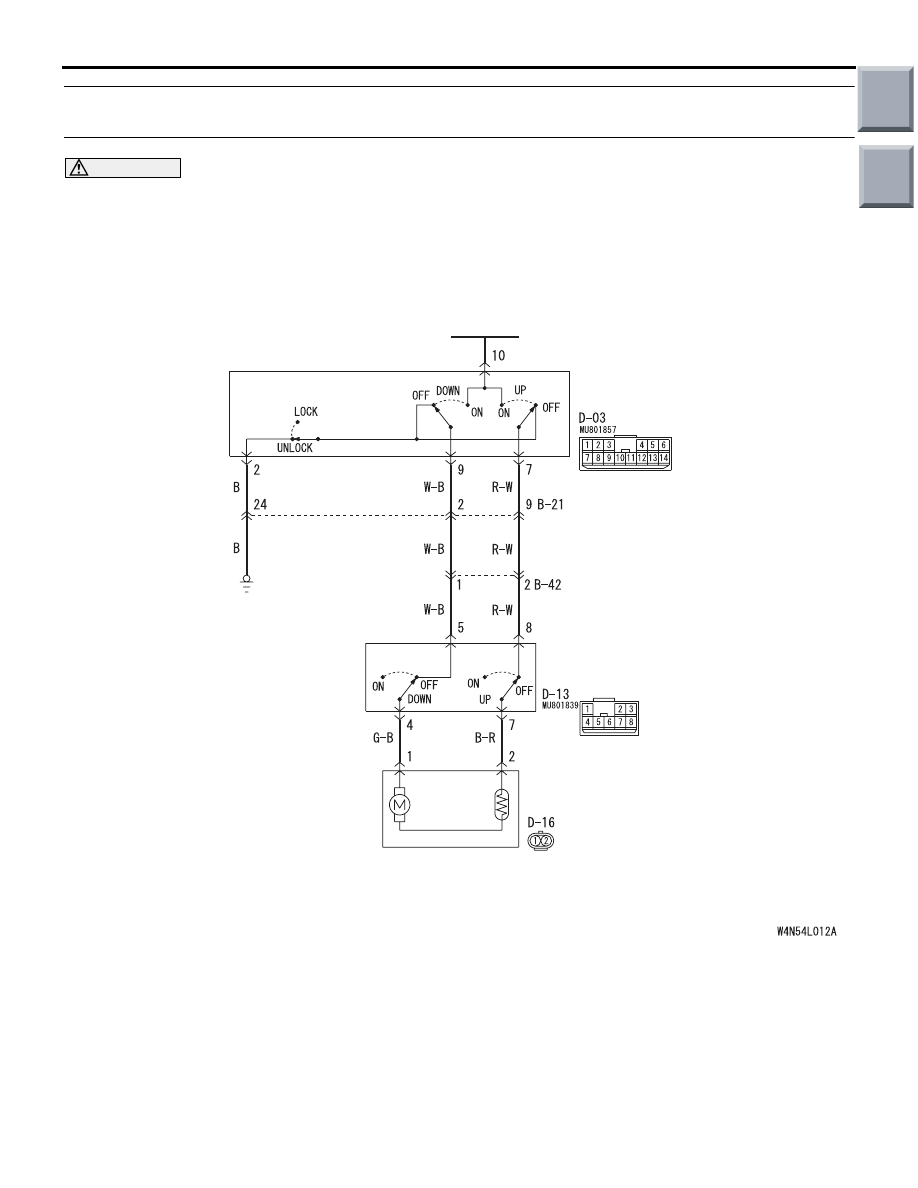
Inspection Procedure D-4: Passenger's and/or rear power window(s) do not work by means of the 
power window main switch.

CAUTION

Whenever the ECU is replaced, ensure that the 
input and output signal circuits are normal.

POWER WINDOW
SUB SWITCH
(FRONT: LH)

POWER WINDOW
MOTOR
(FRONT: LH)

POWER
WINDOW
RELAY

POWER
WINDOW
MAIN SWITCH

(FRONT: LH)

LOCK SWITCH

Power Window (Front: LH) Circuit

Wire colour code
B : Black     LG : Light green     G : Green     L : Blue     W : White     Y : Yellow     SB : Sky blue
BR : Brown     O : Orange     GR : Gray     R : Red     P : Pink     V : Violet   

Main

Index

Group

TOC

SYMPTOM PROCEDURES

SMART WIRING SYSTEM (SWS) USING SWS MONITOR

54C-81

COMMENTS ON TROUBLE SYMPTOM

If the passenger's and/or rear power window does 
not work by means of the power window main switch, 
the power window main switch or the respective 
power window sub switch(es) may be defective.

POSSIBLE CAUSES

• Malfunction of the power window main switch

• Malfunction of the power window sub switch 

(front: LH), power window sub switch (rear: RH) 
or power window sub switch (rear: LH)

• Damaged harness wires and connectors

DIAGNOSIS PROCEDURE

Step 1. Check the power window main switch.
Check that the driver's power window works by 
means of the power window main switch.

Q: Is the check result normal?

YES : 

Go to Step 2.

NO : 

Refer to Inspection Procedure D-2 "Driver's 
power window does not work by means of 
the power window main switch 

P.54C-68

."

Wire colour code
B : Black     LG : Light green     G : Green     L : Blue     W : White     Y : Yellow     SB : Sky blue
BR : Brown     O : Orange     GR : Gray     R : Red     P : Pink     V : Violet   

POWER WINDOW
SUB SWITCH
(REAR: LH)

REAR
POWER WINDOW
SUB SWITCH
(REAR: RH)

POWER
WINDOW
RELAY

POWER WINDOW MAIN SWITCH

LOCK
SWITCH

(REAR: LH)

(REAR: RH)

Power Window (Rear) Circuit

POWER WINDOW
MOTOR
(REAR: RH)

POWER WINDOW
MOTOR
(REAR: LH)

Main

Index

Group

TOC

SYMPTOM PROCEDURES

SMART WIRING SYSTEM (SWS) USING SWS MONITOR

54C-82

Step 2. Check the power window sub switch.
Check that each power window works by means of 
the respective power window sub switch when the 
power window lock switch is turned off.

Q: Is the check result normal?

YES : 

Go to Step 3.

NO : 

Refer to Inspection Procedure D-3 
"Relevant power window(s) do not work by 
means of the front and rear power window 
sub switches 

P.54C-71

."

Step 3. Retest the system.
Check that the rear left power window works by 
means of the power window main switch.

Q: Is the check result normal?

YES : 

The trouble can be an intermittent 

malfunction (Refer to GROUP 00 

− How to 

use Troubleshooting/inspection Service 
Points 

− How to Cope with Intermittent 

Malfunction 

P.00-13

).

NO : 

Replace the power window main switch.

Inspection Procedure D-5: The power window timer function does not work normally.

CAUTION

Whenever the ECU is replaced, ensure that the 
input and output signal circuits are normal.

COMMENTS ON TROUBLE SYMPTOM

If the power window timer function does not work 
normally, these input signal circuit(s), the 
ETACS-ECU may be defective.

POSSIBLE CAUSES

• Malfunction of the driver's door switch

• Malfunction of the passenger's door switch

• Malfunction of the ETACS-ECU

• Damaged harness wires and connectors

DIAGNOSTIC PROCEDURE

Step 1. ECU check by using the SWS monitor
Check that the power supply and earth lines to the 
ETACS-ECU and the SWS communication lines are 
normal.

• Ignition switch: ON

ECU TO BE CHECKED

• ETACS ECU

OK: "OK" is displayed on the "ETACS ECU" 
menu.

Q: Is the check result normal?

YES : 

Go to Step 2.

NO : 

Refer to Inspection Procedure A-3 
"Communication with the ETACS-ECU is 
not possible 

P.54C-41

."

Step 2. SWS monitor data list
Check the SWS communication signal, which are 
related to the power window timer function.

<Selected item> ETACS ECU

• Turn the ignition switch from the ON to the OFF 

position.

• Driver's door: open

OK: Normal conditions are displayed for all 
the items.

Q: Are the check results normal?

Normal conditions are displayed for all the items. : 

Go to Step 3.

Normal condition is not displayed for item No.30 : 

Refer to inspection procedure N-2 "The 
ignition switch (IG1) signal is not received 

P.54C-203

."

Normal condition is not displayed for item No.32 : 

Refer to inspection procedure N-3 "The 
driver's door switch signal is not received 

P.54C-205

."

Item No.

Item name

Normal 
condition

Item 30

IG SW IG1

OFF

Item 32

DR DOOR SW

ON

Main

Index

Group

TOC

SYMPTOM PROCEDURES

SMART WIRING SYSTEM (SWS) USING SWS MONITOR

54C-83

Step 3. ETACS switch data by using the SWS 
monitor
Check the SWS communication signal, which are 
related to the power window timer function.

• Passenger’s door: Close → Open

OK: Normal condition is displayed.

Q: Is the check result normal?

YES : 

Go to Step 4.

NO : 

Refer to inspection procedure N-14 "The 
passenger's door switch signal is not 
received 

P.54C-234

."

Step 4. Retest the system
Check that the power window timer function works 
normally.

Q: Is the check result normal?

YES : 

The trouble can be an intermittent 

malfunction (Refer to GROUP 00 

− How to 

use Troubleshooting/inspection Service 
Points 

− How to Cope with Intermittent 

Malfunction 

P.00-13

).

NO : 

Replace the power window main switch.

Inspection Procedure D-6: The window glass lowers automatically while it is rising.

CAUTION

Whenever the ECU is replaced, ensure that the 
input and output signal circuits are normal.

COMMENTS ON TROUBLE SYMPTOM

If the sliding resistance is too great when the window 
is being raised or the window glass encounters an 
object, the window glass will lower by approximately 
150 mm.

POSSIBLE CAUSES

• Improper adjusted door window glass

• Incorrectly installed or warped glass slider

• Malfunction of the power window motor

• Malfunction of the window regulator

DIAGNOSIS PROCEDURE

Step 1. Check the power window operating 
current.
Check that the power window operating current is 
normal (Refer to GROUP 42 

− Door − On-vehicle 

service 

P.42-35

).

Q: Is the check result normal?

YES : 

Adjust the door window glass (Refer to 

GROUP 42 

− Door − On-vehicle service 

P.42-34

), and then go to Step 2.

NO : 

Replace the defective power window motor 
assembly which operating current are 
abnormal.

Step 2. Check that the door window glasses are 
installed correctly.
Check that the door window glasses are installed 
correctly. Refer to GROUP 42 

− Door − On-vehicle 

Servic

P.42-34

.

Q: Is the check result normal?

YES : 

Go to Step 3.

NO : 

Adjust the door window glass (Refer to 
GROUP 42 

− Door − On-vehicle service 

P.42-34

).

Step 3. Retest the system.
Check that the power window does not lower auto-
matically while it is being raised.

Q: Is the check result normal?

YES : 

The trouble can be an intermittent 

malfunction (Refer to GROUP 00 

− How to 

use Troubleshooting/inspection Service 
Points 

− How to Cope with Intermittent 

Malfunction 

P.00-13

).

NO : 

Replace the power window motor assembly 
of the defective window.

Item No.

Item name

Normal 
condition

Item 05

PASS DOOR SW

from OFF 
to ON

Main

Index

Group

TOC


Content   ..  391  392  393  394   ..