Mitsubishi Colt Ralliart. Manual - part 363


  Index      Mitsubishi     Mitsubishi Colt Ralliart - service repair manual


Search            


Content   ..  361  362  363  364   ..


Mitsubishi Colt Ralliart. Manual - part 363


SYMPTOM PROCEDURES

SMART WIRING SYSTEM (SWS) NOT USING SWS MONITOR

54B-196

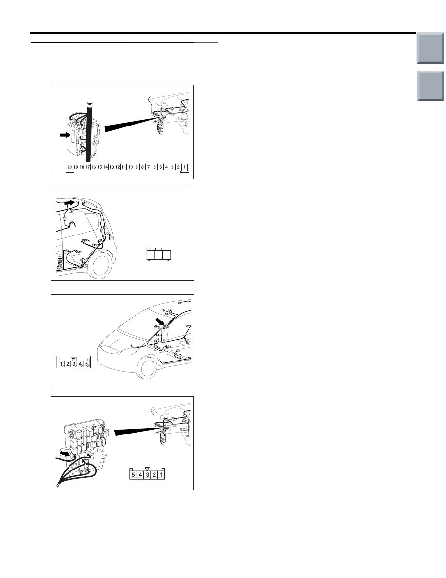
Step 8. Check the wiring harness from B-134 
ETACS-ECU connector terminal No.18 to C-11 
luggage compartment lamp connector terminal 
No.1

NOTE: 

Prior to the wiring harness inspection, check interme-
diate connector C-02 and junction block connector 
B-113 repair if necessary.

• Check the input and output lines for open circuit.

Q: Is the check result normal?

YES : 

The trouble can be an intermittent 

malfunction (Refer to GROUP 00 

− How to 

use Troubleshooting/inspection Service 
Points 

− How to Cope with Intermittent 

Malfunction 

P.00-13

).

NO : 

Repair the wiring harness.

AC313826

Connector: B-134

AG

Junction block side

Junction block (Rear view)

AC401059

Connector: C-11

Harness side

AD

3

1

2

AC401057

Connector: C-02

AD

AC313824

Harness side

AB

Connector: B-113

Junction block (Front view)

Main

Index

Group

TOC

SYMPTOM PROCEDURES

SMART WIRING SYSTEM (SWS) NOT USING SWS MONITOR

54B-197

Step 9. Check the wiring harness from C-11 
luggage compartment lamp connector terminal 
No.2 to body earth.

NOTE: 

Prior to the wiring harness inspection, check interme-
diate connector C-02 and junction block connector 
B-113 and B-130 repair if necessary.

• Check the earth wires for open circuit.

Q: Is the check result normal?

YES : 

The trouble can be an intermittent 

malfunction (Refer to GROUP 00 

− How to 

use Troubleshooting/inspection Service 
Points 

− How to Cope with Intermittent 

Malfunction 

P.00-13

).

NO : 

Repair the wiring harness.

AC401059

Connector: C-11

Harness side

AD

3

1

2

AC401057

Connector: C-02

AD

AC313824

Harness side

AB

Connector: B-113

Junction block (Front view)

AC313826

Harness side

AE

Connector: B-130

Junction block (Rear view)

Main

Index

Group

TOC

SYMPTOM PROCEDURES

SMART WIRING SYSTEM (SWS) NOT USING SWS MONITOR

54B-198

INSPECTION PROCEDURE M-4: The door-ajar warning lamp does not illuminate/extinguish normally.

CAUTION

Whenever the ECU is replaced, ensure that the 
input and output signal circuits are normal.

COMMENTS ON TROUBLE SYMPTOM

If the door-ajar warning lamp does not work normally, 
the input signal circuit or the ETACS-ECU may be 
defective.

POSSIBLE CAUSES

• Malfunction of the all door switches

• Malfunction of the combination meter

• Malfunction of the CAN bus line

• Malfunction of the ETACS-ECU

• Damaged harness wires and connectors

DIAGNOSIS PROCEDURE

Step 1. Check the power supply circuit.
When the ignition switch is turned to the LOCK 
(OFF) position, check if the hazard warning lamps 
illuminate.

Q: Is the check result normal?

YES : 

Go to Step 2.

NO : 

Refer to Inspection Procedure A-2 "When 
the ignition switch is at the LOCK (OFF) 
position, the functions do not work normally. 
Check the battery power supply circuit to 
the ETACS-ECU 

P.54B-43

."

Step 2. Pulse check
Check the input signals below which are related to 
the door-ajar warning lamp.

OK: The M.U.T.-III sounds or the voltmeter 
needle fluctuates.

Q: Is the check result normal?

All the signals are received normally. : 

Go to Step 

3.

The ignition switch (IG1) signal is not received. : 

Refer to Inspection Procedure N-2 "The 
ignition switch (IG1) signal is not received 

P.54B-202

."

All the door switch signals are not received. : 

Refer to Inspection Procedure N-10 "All the 
door switch signals are not received 

P.54B-219

."

Step 3. M.U.T.-III CAN bus diagnostics
Use the M.U.T.-III to diagnose the CAN bus lines.

Q: Is the check result normal?

YES : 

Go to Step 4.

NO : 

Repair the CAN bus line (Refer to GROUP 
54D, Diagnosis 

P.54D-13

).

ETACS-
ECU

SPEED SIGNAL

COMBINATION
METER

CAN COMMUNICATION LINE
(CAN_L LINE)

CAN COMMUNICATION LINE
(CAN_H LINE)

INPUT SIGNAL

INPUT SIGNAL

· IGNITION SWITCH (IG1)
· ALL DOOR SWITCH
· TAILGATE SWITCH

Door-Ajar Warning Lamp Function

System switch

Check condition

Ignition switch (IG1)

When turned from ACC 
to ON

All of the door switches

A door is opened when 
all the doors are closed

Main

Index

Group

TOC

SYMPTOM PROCEDURES

SMART WIRING SYSTEM (SWS) NOT USING SWS MONITOR

54B-199

Step 4. M.U.T.-III other system diagnosis code
Check whether the combination meter-related diag-
nosis code is set.

Q: Is the diagnosis code set?

YES : 

Diagnose the combination meter (Refer to 

GROUP 54A 

− Troubleshooting 

P.54A-31

).

NO : 

Go to Step 5.

Step 5. M.U.T.-III actuator test
Perform the actuator test for the combination meter, 
and check that the door-ajar warning lamp illumi-
nates (Refer to GROUP 54A 

− Combination Meter 

P.54A-62

).

Q:  Is the check result normal?

YES : 

Replace the ETACS-ECU.

NO : 

Replace the combination meter.

Main

Index

Group

TOC


Content   ..  361  362  363  364   ..